In the field of CNC lathe processing multi-process small shaft workpieces, some enterprises are still relying on traditional human loading and unloading of workpieces, which is not only inefficient, but also difficult to meet the needs of modern manufacturing for automation and intelligence.
For this reason, the exploration and implementation of industrial robot-based auxiliary system is particularly urgent.
An industrial robot-assisted loading and unloading system for CNC lathes can successfully replace manual loading and unloading operations. It also ensures production stability and efficiency.
At the same time, it helps realize a more economical and environmentally friendly production model.
In view of this, the article presents the design of a CNC lathe automatic loading and unloading system.
The system is intended to provide automated loading and unloading solutions for enterprises. Its goals are to improve production efficiency, reduce labor costs, and contribute to the development of automation in the CNC lathe industry.
Design requirements
In traditional CNC lathe machining, manual loading and unloading has greater safety risks, such as workpiece slippage, collision, etc. The use of robots for automatic loading and unloading can effectively avoid these safety risks.
The robot uses precise control and protection to prevent worker injury during loading and unloading. It also protects machines and workpieces.
The automatic loading and unloading system designed in the article adopts a CNC lathe with the FANUC&OT system.
The rotary diameter of the lathe is 520 mm, the machining range is 260 mm × 530 mm and the spindle speed ranges from 35 to 3,500 r/min.
The rapid traverse speed is 12,000 mm/min for the X-axis and 15,000 mm/min for the Z-axis.
Based on high enterprise demand for screw nut parts, the target workpiece requires two machining processes. CNC lathe machining is shown in Figure 1.
The machining time of the first process is 51 s, and the machining time of the second process is 53 s. The first processing time is 51 s, and the machining time of the second process is 53 s.
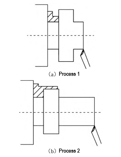
Figure 1 CNC lathe machining process map
Robot selection
CNC lathe is precision machining equipment, widely used for shafts and disk parts manufacturing. To automate production, CNC lathe, robot, and feeding system usually form an automatic loading and unloading system.
The robot is divided into two types based on its relation to the CNC lathe: external and built-in.
External robots use a transmission device to cooperate with the lathe for workpiece loading and unloading. Built-in robots are embedded in the lathe and connect directly to its various parts.
The truss robot is a built-in robot that realizes the positioning and loading/unloading of workpieces through the joint motion of three axes.
This type of robot adopts a rigid structure with high stability and load-bearing capacity, and is suitable for the processing of large and heavy parts.
Articulated robot belongs to a kind of external robot, which realizes more flexible and complex loading and unloading operations through the joint motion of six axes from J1 to J6.
Truss robots have a simple structure and fewer components. They offer a price advantage, support loads up to 100 kg, and feature easy-to-learn motion programming.
The truss robot also faces some limitations. Its limited degrees of freedom make it a little less flexible, which makes it more difficult to install and calibrate.
At the same time, their reusability after disassembly is not high, and some designs may even collide with the machine tool, which may lead to positional shifts under long-term operation.
Articulated robots have a high degree of freedom and excellent flexibility. They occupy a small footprint and offer greater programming freedom.
Their control is more flexible, and they can be applied in a wide range of scenarios. In addition, they have a high reuse rate after disassembly and relatively low maintenance costs.
Articulated robots cost slightly more than truss robots. During preparation, programming and simulations increase the setup time.
Comprehensive comparison, the article chooses articulated robots for designing automatic loading and unloading system for CNC lathe.
System Design
The feeding system and the robot system constitute the automatic loading and unloading system of the CNC lathe. The feeding system consists of a flat bin for storing the workpieces to be machined and a support bracket, which is placed on the side of the CNC lathe;
The robot system consists of a robot base and end clamps for gripping workpieces, which are placed in the center of the two CNC lathes. CNC lathe automatic loading and unloading system workflow shown in Figure 2.
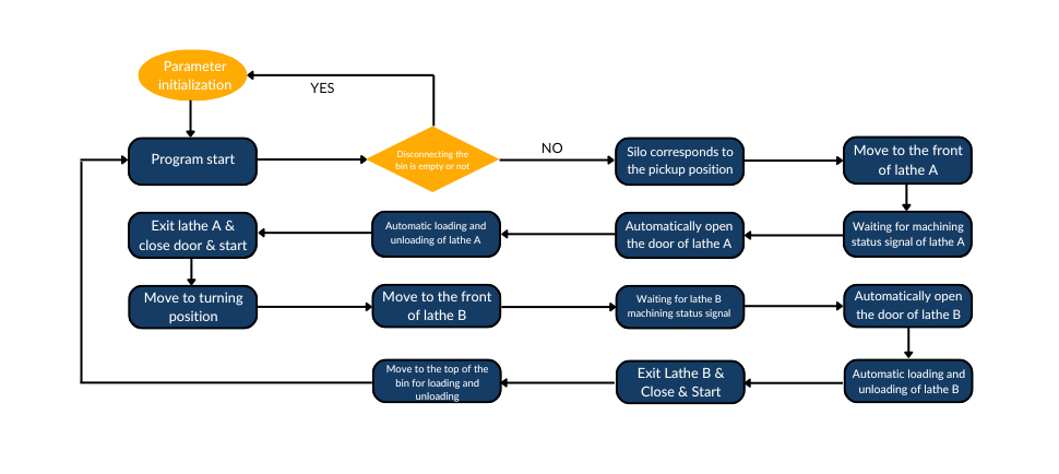
Figure 2 CNC lathe automatic loading and unloading system operation flow chart
When the bin is full, the robot grabs a workpiece from above. It clamps the piece and moves it. The robot places it into the first CNC lathe. The lathe door opens automatically for loading and unloading.
After completing the loading of the workpiece, the robot will exit the working range of the machine tool and automatically close the door of the lathe, and then trigger the machining instructions of the lathe to start machining the workpiece.
Sometimes the workpiece needs flipping for processing. After flipping, the robot restarts and moves the workpiece. It transfers the workpiece to the second CNC lathe. The robot performs the same operation as with the first lathe.
As the workpiece cycles between the two lathes, the robot will move it back to the top of the silo.
It will place the finished workpiece, which has already passed through two processes, in the same position as the first rough workpiece.
This process will be repeated until all rough workpieces in the silo have been taken out and processed.
When the entire bin of blank workpiece processing is complete, the robot system will automatically stop working, and send an alarm signal, prompting the operator to intervene in subsequent operations.
System Optimization
Through production experiments, the phenomenon of robot efficiency over-saturation can be observed.
The speed at which the robot performs actions far exceeds the time required by the lathe to complete the processing task.
As a result, the robot remains in a load-carrying state for a long period while waiting. This prolonged waiting may lead to wear and tear of the robot components, thereby shortening its service life.
Therefore, in order to ensure the double optimization of productivity and equipment durability, the operating speed of the robot is adjusted to achieve a more accurate match with the machining cycle of the lathe.
In view of the robot executing loading and unloading tasks, its travel speed directly determines the time consumption of each action link.
Therefore, speed is regarded as an independent variable, and time is regarded as a dependent variable.
To shorten the standby time, the time gap between lathes must be reduced. The changeover time in one lathe should closely match the machining time of the other.
Based on this principle, a CNC automatic loading and unloading system time planning diagram is constructed.
This diagram reflects the total time required for a set of loading and unloading action processes.
Robot working time planning is shown in Figure 3.
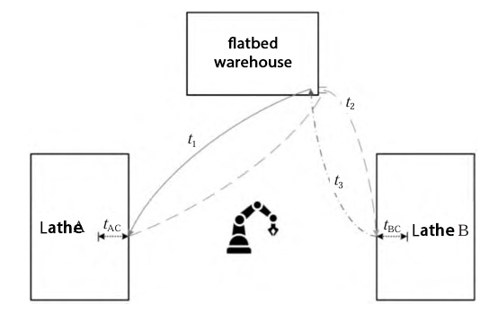
Figure 3 robot working time planning
In order to derive the optimal value of the speed of the automatic lathe loading and unloading system, the length of time consumed by the robot to perform each action process under different speed conditions is recorded.
The relationship between the robot’s operating speed, expressed as a percentage of the maximum speed, and the standby time is shown as a curve in Figure 4.
Figure 4 shows that when the robot running speed is 35% of the maximum speed, its standby time with load is the shortest.
This means that the robot’s wear and tear degree is the lowest at this speed. As a result, the automatic loading and unloading system can maintain a more durable and stable operation.
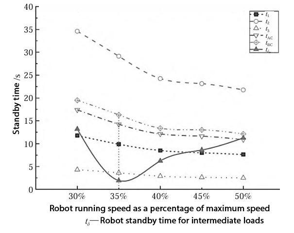
Figure 4 The relationship between the robot running speed of the maximum speed ratio and the standby time of the curve graph
Conclusion
According to the parameters of the CNC lathe and the actual needs of the target enterprises, the article analyzes the advantages and disadvantages of truss robots and articulated robots.
An articulated robot is selected for its flexible motion. It serves in the CNC lathe’s automatic loading and unloading system.
An automated loading and unloading system of the CNC lathe based on industrial robots is constructed.
The performance of the robot is assessed through experiments.
Furthermore, speed optimization of the automated loading and unloading system is carried out.
The speed performance of the system during the operation of each link is analyzed.
Through the experimental calculation fitting, it is found that when the operating speed of the system is 35% of the maximum speed, the system has the lowest degree of wear and tear, which can maximize the operating efficiency of the system.