Starting from the analysis of urea gear pump gear processing technology, based on the principle of precision cutting, designed a set of gear shaping cutting fixtures, and introduced the work process of the fixture. A detailed description of the gear precision cutting fixture positioning, cutting,g, and other structural design, and analysis of the main components of the fixture. Fixture by the use of cutting gear surface flat, smooth, burr-free, no cracking, fixture service life is high.
Urea pump gear introduction and processing technology
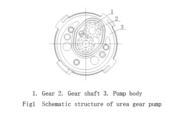
1. Urea Gear Pump Design
The urea gear pump relies on the active gear, driven by the rotation of the driven gear, to change the inlet and outlet volume. This change enables the suction and discharge of the aqueous urea solution in hydraulic pumps, as shown in Figure 1.
2.Gear Materials for Urea Pumps
Gears are the core components of external gear pumps. Traditional gear pumps use materials like steel, cast iron, and non-metals for wear and deformation resistance. However, urea pumps differ. Since the urea solution is corrosive, urea pump gears must be resistant to corrosion. Compared to metal gears, plastic gears offer advantages such as low cost, lightweight, corrosion resistance, self-lubrication, and low transmission noise.
3.PEEK Gear Selection
For this pump, the gear material selected is PEEK (polyether ether ketone) plastic. PEEK is a semi-crystalline polymer with high-temperature resistance, wear resistance, and excellent chemical corrosion resistance. It also has low water absorption, high toughness, and impact resistance.
4.Manufacturing Process for Plastic Gears
Plastic gear manufacturing can be divided into non-cutting and cutting processes:
- Non-Cutting Processing: Methods like injection molding or compression molding, suitable for high-volume, low-precision gears.
- Cutting Processing: Involves turning, milling, gear insertion, or hobbling to meet precise dimensional accuracy and surface roughness requirements, though it is less efficient.
5.Precision Requirements for Urea Pump Gears
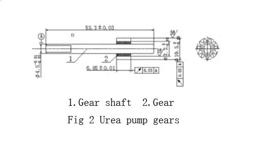
As shown in Figure 2, the urea pump gears require a circular runout of 0.03 relative to the shaft and surface roughness of Ra 0.8. To meet these high-precision requirements, this paper combines both non-cutting and cutting processes for gear production.
Plastic cutting principle and cutting fixture structure
1. PrinciplThe plastic
Plastic cutting involves removing an excess plastic layer from the workpiece, creating chips, and forming a machined surface. This process is an extrusion process.
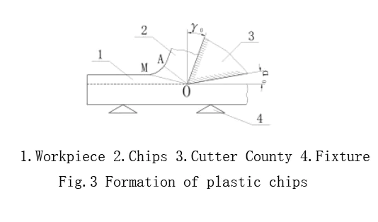
As shown in Figure 3, when using a cutter with a front angle γ0 and rear angle α0 to cut the plastic, the plastic first undergoes elastic deformation, followed by plastic deformation. When the pressure reaches the shear strength, the material shears along the slip surface OA in the OMA area. The cutter continues to move, causing further deformation until the blade fractures, forming chips.
The plastic gear processing in this paper uses a molding method. The cutting tool is shaped like a gear, and the blank plastic gear undergoes precision cutting and molding in one step.
2. Structure
2.1Plastic Gear Precision Cutting Fixture
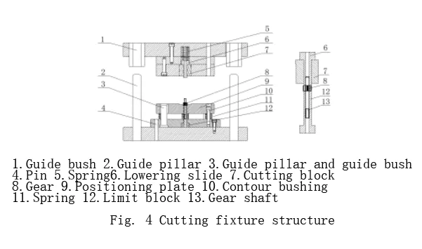
The plastic gear precision cutting fixture is designed for small punch cutting. The structure of the fixture is shown in Figure 4. The workpiece is clamped under the lower pressure slider, with the limit block positioning the piece. The cutting block slides up and down to cut the workpiece.
2.2Roughing and Finishing Process for High Precision Plastic Parts
For high-precision plastic parts, roughing and finishing must be done separately. In rough milling, prioritize efficiency. Select processing parameters that maximize productivity while limiting deformation. Leave about 0.1 mm of machining allowance for finishing.
Before precision cutting, inject a gear blank using mold injection. The gear shaft is inserted into the blank. The overall dimensions of the blank gear are 0.1 mm larger than the drawing on one side.
2.3Gear Cutting Process
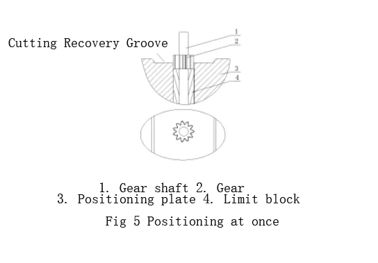
To ensure proper gear shape and position tolerance, position the gear using the gear shaft as a reference. The positioning process is as follows:
2.4Positioning Plate and Limit Block
As shown in Figure 5, process the positioning plate and limit blocks into a gear shape. Ensure a clearance fit. Insert the gear shaft end into the bore of the limit block. Embed half of the gear into the positioning plate groove.
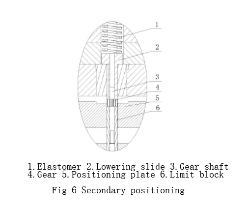
2.5Secondary Positioning
As shown in Figure 6, press the machine down. Insert the other end of the gear shaft into the tlower-pressureure slider bore. The lower pressure slider pushes against the gear, using the spring for secondary positioning.
2.6Gear Cutting Procedure
After positioning the workpiece, follow these cutting steps:
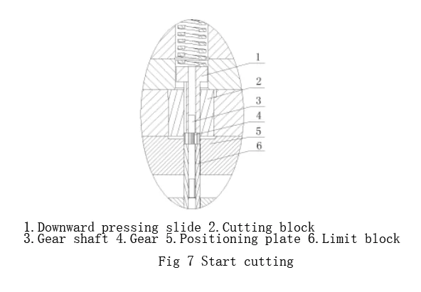
(1)Cutting Starts
As shown in Figure 7, the cutting block begins to cut the gear as the machine presses down.
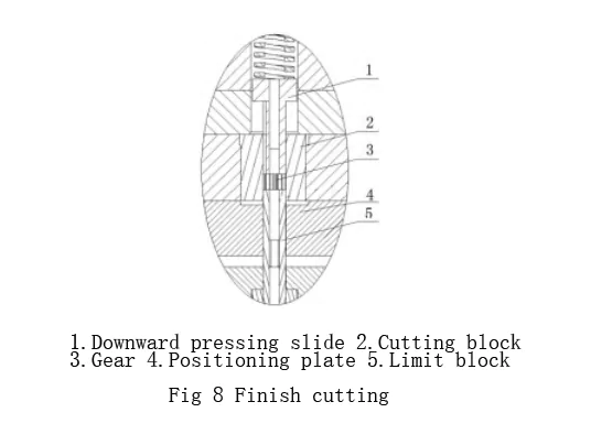
(2)Completion of Cutting
As shown in Figure 8, the machine continues pressing down. The positioning plate and limit blocks push the gear and cut the block into the cutting hole. The cutting process finishes, and waste falls into the chip recycling tank.
The design of the main working parts of the fixture
1. Cutting block
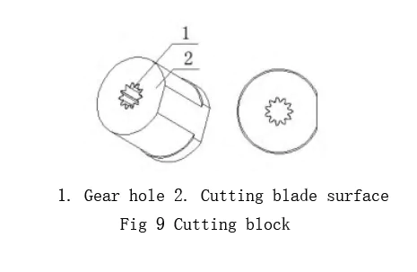
1.1Cutting Block Overview
The cutting block, shown in Figure 9, mainly determines the gear processing accuracy. If the cutting edge wears or the gear hole has roughness, the gear surface roughness will increase. This could even lead to gear cracking. Therefore, the cutting block must have high hardness and low roughness on the cutting surface.
1.2Material and Design of the Cutting Block
Thermoplastic materials have low hardness and require less cutting force. Thus, the tool material should easily form sharp cutting edges. Suitable materials include hardened carbon tool steel, high-speed steel, alloy tool steel, and tungsten-cobalt carbide. For precision machining, diamond-turning tools are a good choice. The cutting block in this fixture is made of tungsten steel (alloy tool steel).
1.3Cutting Block Performance and Design Parameters
The cutting block slides along the downward pressure slider and limit block, making a full circle around the gear. The angle α0 = 0 is optimal for the cutting block.
Front Angle Selection
The size of the front angle γ0 directly affects cutting performance. Factors like plastic-type, tool material, and processing nature influence its size. The front angle balances the cutter head’s stability and sharpness.
- For hard materials, choose a small front angle.
- For soft materials, use a larger front angle.
- In roughing, use a smaller front angle; for finishing, choose a larger one. Typically, the front angle ranges from -5° to 25°. In this case, to ensure gear accuracy and cutting block strength, we select γ0 = 0.
1.4Cutting Block Surface Treatment
The gear hole in the cutting block is processed with a slow-walking wire. The surface roughness ranges from Ra 0.2-0.3 μm, meeting the workpiece drawing requirements. The cutting block’s cutting plane can also be finished using a grinding machine, achieving the same surface roughness (Ra 0.2-0.3 μm).
These processing methods sharpen the cutting edge. As a result, the workpiece’s surface cut by the cutting block remains flat and smooth.
Downward sliding block and limit block
1.1Downward Pressure Slider and Positioning Block
The downward pressure slider and positioning block, shown in Figure 10, are used for workpiece positioning. They ensure the workpiece aligns with the cutting block.
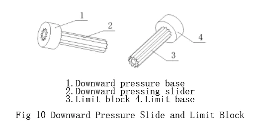
1.2Material and Manufacturing
These components must withstand extrusion and impact, requiring hardness and abrasion resistance. Cr12MoV steel (HRC 58-62) is a suitable material. The slider and block are processed with slow-feeding wire and shaped like gears. The base fits with interference and is welded and ground at the welding points for stability.
1.3Gear Shaft Positioning
The gear shaft ends fit into the limit block and lower pressure slider bores. The gear shaft size is Φ4.5. To maintain concentricity, the bore is 0.05 mm larger than the shaft on one side. To ease the placement of the gear and shaft, the bore ports are chamfered at 0.1 mm × 0.5 mm.
Precision cutting clearance
As shown in Figure 11, the limit block supports the blank gear, while the cutting block slides vertically. For complete cutting, the limit block must penetrate the cutting block. If the limit block’s external gear dimensions are too small, the cutting may cause the plastic gear to collapse or crack.
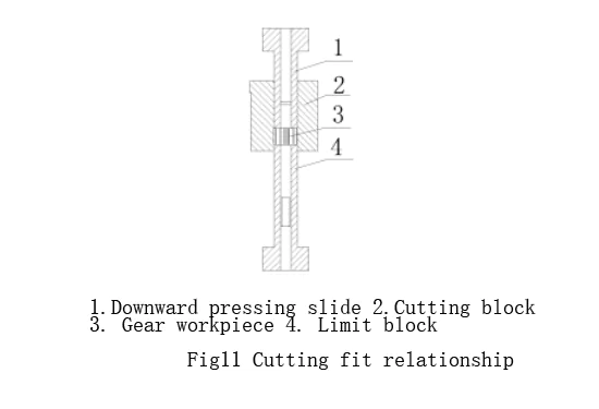
References suggest the double-sided clearance of the convex-concave die should be under 0.01 mm. However, considering fixture manufacturing precision and service life, this requirement is too strict. In practice, a side clearance of up to 0.02 mm between the cutting block and the limit block ensures gear accuracy without causing collapse or cracking.
As shown in Figure 12, during the cutting process, the cutting block slides within the lower-pressure slider. After cutting, the slider pushes the cutting block and workpiece gear hole out. To ensure smooth movement, the gap between the cutting block and slider is about 0.1 mm on each side. Similarly, as shown in Figure 9, the gap between the limiting block and positioning plate is also 0.1 mm on each side for smooth sliding.

Conclusion
This paper applies plastic cutting principles and the characteristics of plastic gears to design a precision cutting fixture. Since mass production began, the fixture has ensured smooth gear surfaces with no collapse or cracking. The round runout is under 0.03mm, meeting the technical requirements for urea gear pumps. Production results confirm that the fixture’s design and material selection are effective, offering high stability and efficiency.