Slender shafts are parts where the length-to-diameter ratio is greater than 25. Examples include light bars and screws.
Despite their simple shape, slender shafts have low stiffness. During turning, cutting force, gravity, and heat can cause vibration.
These shafts are also prone to defects like taper, girdle shape, and bamboo shape. This makes it hard to ensure accuracy.
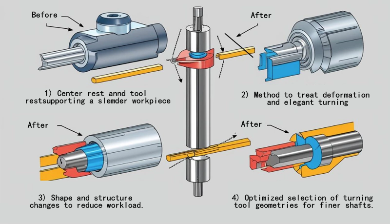
The three key technologies for turning slender shafts include:
(1) Providing auxiliary support using a center stand and a follow tool holder to enhance workpiece stiffness.
(2) Addressing thermal deformation and elongation of the workpiece.
(3) Select the turning tool geometry reasonably.
Problems and measures in slender shaft turning.
In the turning process of slender shafts, thermal deformation, bending deformation, and vibration often occur. These factors affect machining accuracy and surface quality. The following are the measures taken for these problems.
1. Bending deformation caused by heat elongation of the workpiece
During cutting, thermal elongation of the workpiece can cause bending. This may lead to the workpiece getting stuck. To prevent this, the following measures can be taken:
- Flexible Swivel Centers: These centers support the workpiece and compensate for heat-induced elongation.
- Floating Clamping: This allows the workpiece to adjust its position, avoiding bending due to improper clamping.
- Reverse Feed Turning: Reverse feed straightens the cut part and pushes the uncut part, reducing bending.
Additionally, using a “one top, one clamp” method helps. The clamping jaws should not be too long. A steel wire pad in the groove helps maintain floating line contact and prevents bending deformation.
2. Bending deformation and vibration caused by cutting force
In machining, the cutting force can cause the bending of the workpiece. This leads to vibration, affecting precision and surface roughness.
In high-speed cutting, the workpiece’s self-weight, deformation, and vibration have a greater impact. To address this, the following measures can be taken:
- One-top-one-clamp or two-top-center clamping: These methods reduce bending deformation and improve workpiece rigidity.
- Tool holder auxiliary support: Using followers with the turning tool feed can offset back force, improve rigidity, and reduce deformation. This enhances machining accuracy.
These measures reduce bending deformation and vibration, improving machining accuracy and surface roughness.
Thermal deformation and bending in turning slender shafts can be solved with elastic rotary centers, floating clamping and reverse feeding.
Choosing the right clamping method and adding auxiliary support can reduce cutting force impact. This improves workpiece precision and surface quality, leading to better machining results.
Design of Specialized Heel Tool Holder
1. Two-jaw forward turning with the tool holder.
Figure 1 shows a two-jaw forward turning for turning a long and thin shaft with the tool holder. The following tool holder is designed for forward feed turning, and the turning tool is located on the left side of the bearing.
The body of the following tool holder 14 is made of sheet steel and a shank is fixed to a small tool holder 1. The turning tool 4 is supported by two pins 3, which are fixed to the steel plate and held firmly in place by two pressure plates 5.
Two bearings 10 are mounted on an adjustable position steel plate 13 using a shaft 8 and a lock nut 9 so that adjustments can be made for different diameters of shaft material 7. This design can effectively support the turning of slender shafts.
Description of key components
- 1: Small tool holder
- 2, 6, 11: bolts
- 3: Pin
- 4: Turning tool
- 5: Platen
- 7: Slim shaft material
- 8: Shaft
- 9: Lock nut
- 10: Bearing
- 12: Washer
- 13: Adjustable position steel plate
- 14: Tool holder body
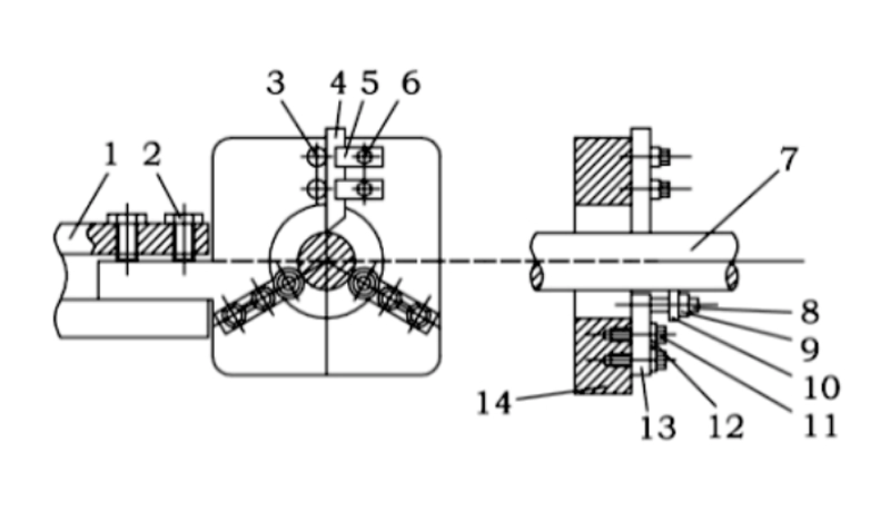
Figure 1: Two jaws forward feeding the following holder
2. 2-jaw reverse turning followers
Figure 2 shows the second type of two-jaw reverse turning followers for turning slender shafts. This design is used for floating clamping and reverse feed turning with the turning tool located on the right side of the bearing.
The body of the following tool holder 14 is also made of sheet steel and a shank is fixed to the small tool holder 1. The turning tool 4 is supported by two pins 3, which are fixed to the steel plate and stabilized by two pressure plates 5.
Two bearings 10 are mounted on an adjustable steel plate 13 using a shaft 8 and a locknut 9, the adjustable plate is adjustable for different diameters of shaft material 7. This design also provides effective support for turning slender shafts.
Description of key components
- 1: Small tool holder
- 2, 6, 11: bolts
- 3: Pin
- 4: Turning tool
- 5: Platen
- 7: Slim shaft material
- 8: Shaft
- 9: Lock nut
- 10: Bearing
- 12: Washer
- 13: Adjustable position steel plate
- 14: Tool holder body
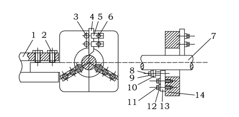
Figure 2: Two-jaw reverse feed tool followers
3. Design Principle of Tool Holder
Through the design of these two tool holders, we see that two supporting claws can meet turning requirements.
In turn, the cutting force and the workpiece’s gravity work together to firmly fit the workpiece between the claws.
The turning tool is fixed against the workpiece. It cannot move, ensuring stable turning and avoiding vibration.
compare
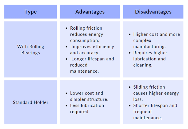
The structure of a tool holder with rolling bearings is similar to a regular tool holder. The main difference is that the front end of the supporting claw has a rolling bearing.
The rolling bearing replaces sliding friction with rolling friction. This gives the tool holder with rolling bearings both advantages and disadvantages.
1. Advantages and disadvantages
2 . Cutting fluid and lubrication requirements
- Original: In the case of rigidly supported tool holders. It is necessary to pour sufficient cutting fluid to minimize the wear of the supporting jaws.
- Rewritten: For rigidly supported tool holders, use enough cutting fluid to reduce wear on the supporting jaws.
- Original: In the case of tool holders with rolling bearings, sealed grease-lubricated rolling bearings are used, thus avoiding the disadvantage of frequent lubrication in the case of rigid supports.
- Rewritten: Tool holders with rolling bearings use sealed grease-lubricated bearings. This avoids frequent lubrication needed for rigid supports.
3. Importance of the contact pressure of the support jaws
The contact pressure of the support jaws needs to be kept within an appropriate range when using a tool holder:
Excessive contact pressure: This can lead to “sliver” shape errors in the workpiece.
Too little contact pressure: if the support jaws do not make contact, the support stiffness will be insufficient and the cutting effect will be poor.
3.1 Problems of rigid support and tool holder
When using a rigidly supported tool holder, it is critical to ensure that each support jaw makes proper contact. This means that each pawl should maintain the same small clearance for free sliding as the inner wall of a precision-fit plain bearing.
To achieve this, the wear of the jaws must be checked and adjusted regularly. However, this process is often time-consuming and difficult to adjust accurately.
3.2 Advantages of rolling bearings
Tool holders with rolling bearings avoid these problems. As the rolling bearing support jaws make full contact with the workpiece, there is usually no risk of too little or no contact pressure, ensuring cutting rigidity and stability.
Conclusion
Turning slender shafts is a technically demanding process that involves the precision of tools, machine tools, a auxiliary tools, as well as the comprehensive consideration of process arrangements and operating skills.
To ensure machining accuracy and efficiency, the operator must have strong professional knowledge and practical experience.
In addition, the turning process often needs to be equipped with some specialized process equipment or auxiliary devices according to the specific situation in order to solve the specific problems in slender shaft machining, such as vibration control and rigidity guarantee.
This technology is not only demanding in terms of equipment but also terms of process organization and operational details.