Manufacturers typically weld the rear axle of heavy-duty vehicles from two shell halves and assemble it with a rear cover, axle flange, and other accessories.
Welding process: stamping → half-shell forming → seam welding → rough boring → welding ring, cover, flanges, and accessories → machining.
Welds include longitudinal seams and circumferential welds at the ring, rear cover, and flanges.
Traditional manual welding poses health risks to workers and leads to reduced productivity and inconsistent quality.
Robotic welding requires rotating, multi-functional fixtures for longitudinal, ring, rear cover, and accessory welds.
Features include axial length adjustment for various shell sizes and automatic positioning and clamping for robotic loading and unloading.
Clamping of different diameters to adapt to the varying diameters of the bridge shell.
The design team developed an intelligent rotary fixture with rotation, clamping, and axial movement mechanisms tailored to these needs.
Artificial welding line welding fixture status
- a single fixed fixture
This fixture clamps both ends with V-type jaws to weld one side’s longitudinal seam in a single pass.
- manual clamping chuck rotary fixture
This fixture clamps shell ends with two manual chucks; one rotates 180° for welding both sides.
Because the fixture all actions rely on manual, there are inconveniences, time-consuming, laborious, and other shortcomings.
- hydraulic clamping chuck rotary fixture
This rotary chuck fixture utilizes hydraulics, but it risks leaks, clogs, contamination, and misfires.
- Rotary fixture rotation mechanism
An ordinary motor drives the rotating mechanism through a reduction gear. However, using a button to control the rotating position results in low accuracy.
No fixture yet ensures eco-friendly, intelligent, and precise welding of bridge shell seams and parts.
Existing fixtures limit automation; high-precision, intelligent, eco-friendly rotary fixtures are essential.
Intelligent welding rotary fixture overall design program
Functional requirements of the fixture
The rotary fixture for bridge shell welding should include these parts based on functional requirements.
- Rotary box part.
Rotary box spindle drive using servo motors through a gear drive to achieve step-less adjustment of the chuck rotation angle.
Install a pneumatic chuck and cylinder at the rotary spindle front for positioning, clamping, and loosening one bridge shell end.
- With the rotary box part.
The rotary box, driven without power, uses a pneumatic chuck and cylinder to position, clamp, and loosen the other bridge shell end.
- Adjust the clamping slide part.
To achieve different lengths of axle shell welding, an adjustable length is required.
The operator adjusts the lower slide using a manual screw with a large stroke, which is used when the axle shell length varies significantly.
The upper slide, driven by a short-stroke pneumatic cylinder, handles positioning, loading, unloading, and clamping of the axle shell.
The designers adopted a double-layer structure to reduce fixture costs and shorten the time required for loading and unloading the bridge shell.
- Fixture base part.
According to the welding line robot operation height requirements, the design of the base part is intended to facilitate the fixed installation of the above parts.
- Electrical automatic control part.
The engineers designed the electrical control system to enable the coordinated and orderly operation of the fixture and the robot.
Overall design of the fixture
According to the above process requirements, the overall design of the fixture is shown in Figure 1.
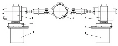
1. Leftbase; 2. Leftadjustmentclampingslide;
3 . Rotarybox; 4. Workpiece(bridge shell);
5. Rotatingbox; 6. Rightadjustmentclampingslide;
7. Rightbase
Fig.1 Schematic assembly of rotary table
Fixture principle: The Robot loads the bridge shell into the fixture. The left and right rotary boxes move the center; pneumatic chucks clamp the workpiece ends. The robot releases its jaws and leaves.
The welding robot welds the workpiece. As for the welding workpiece parts, according to the welding line process layout.
For middle-section welding, the fixture welds one shell half, then rotates 180° to weld the other.
If welding a flange or a shaft head, it is necessary to rotate the bridge shell uniformly at a certain speed during the welding process.
When welding attachments, the workpiece either rotates or remains stationary, as required by the process.
Structural design of the main parts of the fixture
Rotary box design
The rotary box, the fixture’s core, powers rotation and must allow step-less speed adjustment to match welding needs.
According to the requirements of the rotary box function, the design of the rotary box structure is shown in Figure 2.
After installing the bridge shell, the clamping button activates cylinder 3 to clamp, reverse to loosen, and control rotation.
Loosening the workpiece reverses clamping. Chuck rotation is driven by servo motor two via planetary reducer one and gears 9, spinning spindle five at the set speed.
The servo motor controls rotary speed and position with feedback; the pneumatic gripper controls the axis.
The pneumatic gripper is used for clamping and unclamping, which is fast, clean, environmentally friendly and safe.
The rotary box on the left adjustable slide moves to the center position and clamps the workpiece end, then returns for loading and unloading.
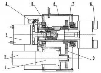
1. Planetary gearbox; 2. Servomotor; 3. Clamping cylinder;
4. Electric conversion mechanism; 5. Rotarymainshaft;
6. Rotaryboxbody; 7.Pullingrod; 8. Pneumatic chuck;
9. Gearpair
Fig.2 Structured diagram of hydraulic rotary table transmission device
Design of the follower box
The rotary box, a core fixture component, rotates the workpiece but has no own power, acting as a follower (see Figure 3).
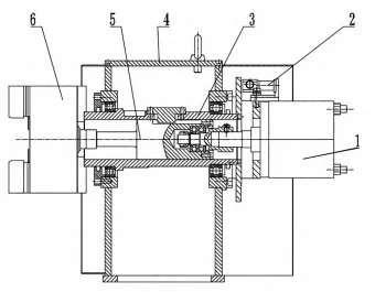
1. Clamping cylinder; 2. Electricconductionmechanism;
3. Rotarymainshaft; 4. Rotatingboxbody;
5. Pullingrod; 6. Pneumatic chuck
Fig.3 SchematicdiagramofCNCrotarytabletransmissiondevice
The rotary box, made of pneumatic cylinder 1, spindle 3, box 4, and chuck 6, supports, locates, clamps, and rotates the workpiece’s right end.
The following rotary boxes are independent, spaced to fit the workpiece length, and allow loading/unloading.
The rotary box on the right, adjustable slide moves to center position and clamps the workpiece end, then returns for loading and unloading.
The design of adjusting clamping slide table
The clamping slide’s upper and lower structures adjust the distance between the rotary and follow chucks.
The upper slide 5 is driven by cylinder 3 to facilitate the loading and unloading of the workpiece, as well as automatic positioning and clamping.
If the shell exceeds the cylinder stroke, adjust the lower slide using screw nut 2 to ensure proper handling.
Left and right clamping slides adjust rotary box positions to enable workpiece loading and unloading.
The structure of the adjusting and clamping slide is shown in Fig. 4.
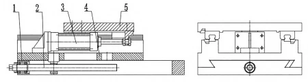
1.Slidebody; 2.Manualscrewpair; 3.Pneumaticcylinder; 4.Lowerslide;5.Upperslide
Fig.4 Schematic diagram of the CNC rotary table transmission device
Conclusion
This paper presents an intelligent rotary fixture equipped with a servo-driven spindle and pneumatic loading and clamping capabilities for versatile bridge shell welding.
The fixture in a bridge shell welding line coordinates with robots and is programmed for the automatic welding of different parts.