Machine tool fixtures are fundamental process equipment. They act as the interface between the workpiece and the machine tool. They also connect with cutting tools, robots, and other equipment. Their flexibility greatly affects modern manufacturing technology.
Flexibility refers to variable or adaptable fixture flexibility refers to the fixture of different shapes and sizes of parts adaptability.
To improve product competitiveness, most enterprises use small-batch production. This leads to higher demands for flexibility. Modern manufacturing technology must adapt. Machine tool fixtures especially need greater flexibility.
Flexible fixtures form a large family. This includes combination fixtures, programmable fixtures, and general-purpose flexible fixtures. Fixtures using phase-change materials also belong to this category. These are referred to as phase-change material fixtures. They are divided into two types. One type is true phase-change material fixtures. The other is pseudo phase-change material fixtures.
Can be used for machine tool fixtures of the truth change material more use of different phase change materials can be obtained from a variety of types of fixtures see Figure 1.
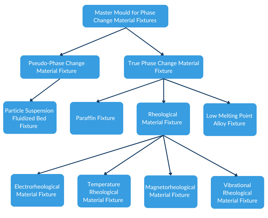
Figure 1 Phase change material flexible fixture family
Truth change material fixture
Fixture phase change materials in the “phase change” term is limited to solid, liquid phase transition.
In a certain temperature and pressure conditions almost all materials can be solid, liquid phase transition.
In this paper, the phase change material refers to room temperature, normal pressure conditions can be solid, liquid phase transition and reversible phase change of those materials.
Specifically, the phase transition temperature of the phase change material must be allowed for the machine tool – fixture – workpiece system.
Too high or too low a temperature on the machine tool, especially on the accuracy of the workpiece must be limited.
The phase change temperature requirements for machine tool fixtures are roughly between room temperature and 100°C. The phase change temperature for the machine tool fixtures is approximately 100°C.
The mounting and dismounting of workpieces on machine tool fixtures requires a reversible phase change of the phase change material.
Fixtures based on phase change materials have the unique property of having a large clamping force area and a uniform clamping force.
Especially suitable for weak stiffness and complex shape parts, these parts are placed in the liquid phase of the phase change material. Then, under certain external stimulus conditions, the phase change material quickly transforms into a solid state. This enables uniform clamping of the workpiece.
When processing is completed, the phase change material quickly returns from the solid state to the liquid state. This allows the workpiece to be easily removed.
The following highlights several types of phase change material fixtures capable of performing the above functions.
(1) Low melting point alloys and paraffin fixtures
The most easily thought of phase change materials are low melting point alloys such as lead-tin-bismuth (32% Pb, 16% Sn, 52% Bi) with a melting point of 95°C. Changing the ratio of this alloy can further reduce the melting point.
The melting point of the alloy can be further reduced by changing the proportion of the alloy.
For example, if the above alloy takes 18% Pb, 16% Sn, 49∙4% Bi and then adds 21% In (indium), the melting point temperature is 58°C and can be used for flexible fixtures.
IIn addition, some non-metallic properties are also ideal. For example, paraffin wax has a melting point of 48°C to 58°C. Different grades have different melting points. The melting point of ash is between 80°C and 85°C. These are more ideal phase change materials.
If the shape of the part to be processed is large, the amount of phase change material will increase. Consequently, the heat required to change the solid-liquid phase will also increase. This can sometimes be uneconomical.
In addition, low melting point alloys or waxes will adhere to the surface of the part and are not easily removed. These factors often limit the use of low melting point materials in fixturing applications.
(2) Current-change material fixtures
Temperature is the main external cause of phase change in phase change materials but temperature is not the only stimulus.
In addition to temperature, the external conditions that cause phase change materials to undergo phase change include electric and magnetic fields and vibration.
Sensitive to these external conditions (also known as stimulation) of the phase change material is correspondingly called the current change material, magnetorheological material, vibration-stimulated rheological material, pressure-stimulated rheological material and so on.
Typical Electrorheological fluids are called ER materials, which are composed of a low insulating liquid and an insulating object suspended in it.
When an ER material is exposed to an electric field, its viscosity magically increases.
When the electric field exceeds a critical value, the ER material becomes a solid, and its shear modulus increases as the electric field is further increased.
This phase transition occurs within about 1 ms and is reversible when the external electric field is removed.
This valuable property was soon noticed by the industry, some scholars have begun to study the application of ER materials in the automotive and aerospace industries, such as clutches, brakes, valves, suspension systems.
In 1995, the author in the United States SIU engaged in phase change material flexible fixture research to achieve a thin shell space curved parts of the flexible positioning and clamping.
Figure 2 shows the research work used in the current variable material TPAI3565 shear stress curve.
The shear stress of the ER material can reach up to 14 kPa when a 5 kV field is applied to the ER material at operating temperature.
Although the shear stress of the ER material is only a few ten-thousandths of the shear stress of ordinary carbon steel, it is still satisfactory for finish machining due to the large total surface area of complex parts.
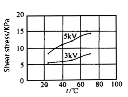
Figure 2 TPAI3565 Shear Stress Curve
(3) Magnetorheological material fixtures
Phase change materials that are sensitive to applied magnetic fields are called magnetorheological materials (Magne-torheological) or MR materials for short.
Magnetorheological materials can be subjected to instantaneous phase changes by applying a magnetic field.
The simplest magnetorheological materials are made by mixing iron powder with a certain percentage of corn oil, or by mixing carbonyl iron with silicone oil.
Magnetorheological materials in the solid phase are much more capable of withstanding shear than galvanic materials.
According to the latest research results the shear modulus of MR materials can reach 0∙5MPa~2∙0MPa, which is about 100 times higher than the corresponding shear stress of current ER materials.
Thick mixtures (weight ratio of 9:1) have been reported, with air permeability data ranging from 4 to 8 times. This air permeability is considered a very good value for engineering applications.
Magnetorheological materials in the clutch and solve the problem of sealing and other research has made some progress, but in the fixture on the application has not been reported.
In the author’s research work, magnetorheological materials have been used for carbon steel valve plate hardened flat grinding process (Figure 3) achieved better results.
Valve plate parts are very thin not only quenched easily deformed grinding is also easy to deform.
When processed on a surface grinder, the valve piece is tightly adhered to the electromagnetic table by the suction force of the electromagnetic suction cup. After grinding, it is difficult to control the flatness of the valve piece due to rebounding when it is released.
This deformation can be minimized by using MR material. A layer of MR material is uniformly applied to the surface of the electromagnetic table of an ordinary surface grinder, and then valve parts are placed on top of it.
Since the MR material is now in liquid form, it is free to fill the gap between the valve plate and the solenoid table.
When the electromagnetic table suction button is pressed, the MR material and the valve piece enter a strong magnetic field. The MR material in the gap instantly solidifies in the magnetic field. It resists part of the valve piece’s deformation. This helps improve the flatness of the valve piece.
And then flip grinding can correct most of the unevenness repeated grinding can get more ideal results.
In the experiment, the flatness of the finished surface of the valve plate can be improved from 15μm to 3μm, which greatly improves the flatness of the two planes of the valve plate after grinding.
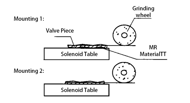
Fig. 3 Improvement of the quality of flatness grinding of valve disc by using MR material
Pseudo-phase change material flexible fixture
Pseudo-phase change material, in contrast to true phase change material, uses a physical method to force the material to transition between the “solid state” and “flow state.” This transformation is called pseudo-phase change, which appears to be a phase change but, in fact, is not.
Typical methods use pressure to force the material to solidify. A stream of air blows to force the material to flow up. This is also known as fluidized bed fixtures.
Gandhi and Tompson have done a lot of work on fluidized bed fixtures, and Figure 4 shows one of their experimental setups when they developed the fluidized bed fixture.
Figure shows that when the hydraulic chuck applies pressure to the pressure plate. It compacts the bed material (steel balls or other particulate material) and firmly “fixes” the workpiece. At this point, the workpiece is like a planted tree buried in the solid bed material.
When the parts are processed, the hydraulic chuck force releases the pressure plate. At the same time, high-pressure air is blown into the container below the hole. This causes the bed material to bulge and become loose, allowing the workpiece to be pulled out smoothly.
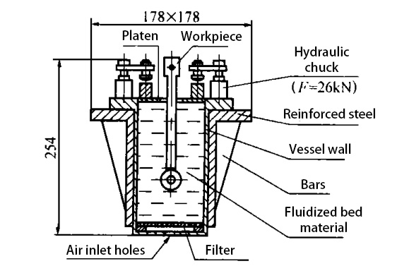
Figure 4 Fluidized bed flexible fixture experimental device
Figure 4 is only a test of the clamping force of the experimental device schematic so the positioning elements of the fixture is not drawn.
In fact, the positioning elements are shown in the figure. These may include positioning planes, pins, or blocks. They are placed to avoid contact with suspended particles. This ensures the workpiece does not touch particles near its positioning surface.
Therefore, the combined force of the suspended particles on the workpiece when it is clamped will always keep the workpiece against the locating element in accordance with the principles of fixture design.
The fixture has a high capacity for holding the workpiece. A 25∙4mm x 25∙4mm cross-section workpiece requires a force of 1kN to be pulled out of the fixture at a bed material compression of 38MPa.
In addition, it is sufficiently stiff that Jeries et al. used a 30 mm diameter, 300 mm long mandrel inserted to a depth of 152 mm in their experimental fluidized bed fixture.
The mandrel was tightly fixed when a pressure of 690 kPa was applied to the fluidized bed.
Their experiments showed that after applying a lateral force of 123N to the upper end of the mandrel, the mandrel was displaced by only 25∙4μm.
When the force was increased to 500 N, the mandrel displacement was 60 μm. This displacement would have been smaller if the embedded part had a larger surface area. A more complex shape would also help reduce the displacement.
Obviously, this fixture can meet general finishing and semi-finishing work requirements. The larger the surface area of the clamped part, the more complex its shape, the higher the clamping reliability.
In addition, this fixture can be applied to a variety of parts of completely different shapes and sizes, with great flexibility and good practical value.
In short, the clamping force of phase change materials covers a large area. The clamping force is uniform. It is especially suitable for clamping parts with weak stiffness and complex shapes.
The phase change material fixture has a simple structure. Its clamping and loosening are controllable, making fixture installation automation easy to achieve.
With the rapid development of electronic technology, computer technology and modern materials science phase change material fixture has a very broad development prospects.
Conclusion
Manufacturing is evolving toward more flexibility and customization. Advanced fixture technologies are becoming vital tools. Fixtures using phase-change materials are especially important. They improve precision, efficiency, and adaptability.
These intelligent fixtures respond to various stimuli. Stimuli include temperature, electrical, magnetic, or pneumatic inputs. Such fixturing solutions enable smarter machining. They also enhance system responsiveness and flexibility.