Fixture design plays a vital role in the mechanical manufacturing process, it is used to fix, clamp and guide the workpiece device to ensure the accuracy and stability of the workpiece processing.
Before designing fixtures, it’s essential to understand the workpiece’s processing requirements and workflow. Communicate with process engineers to grasp its shape, material, size, and precision needs. Also, clarify machining steps and time estimates. Based on this, determine the fixture’s clamping and positioning plan.
About rotary table and tailstock
The rotary table is a common component in CNC machines. It enables continuous rotation and multi-face machining of the workpiece.
The CNC rotary table works by rotating the table to complete machining tasks, enabling precise multi-angle operations.
This equipment is ideal for plate and box-type parts. It supports CNC-controlled automatic indexing and positioning for complex tasks.
The tailstock works with the rotary table to ensure stability. It’s used together when the fixture length exceeds 400 mm.
Clamping and positioning program to confirm the body
Modern machining fixtures often use two-hole positioning on one side. This is common in complex automotive box parts. Designers usually include these positioning holes in the part design to improve fixture accuracy.
Figure 1 shows a car box parts, the left side of the picture for the parts of the horizontal placement of the top view, the right side of the picture for the parts of the longitudinal placement of the elevation diagram.
This part has machining requirements on six sides. Using an ordinary 3-axis CNC machine would require over eight processes and more than eight sets of fixtures to complete.
Considering efficiency and cost, we use a 3-axis CNC machine with a high-precision rotary table. This setup allows the part to be processed in just two operations.
One of the process (as shown in Figure 1, the left side) product placement, processing position: top view direction, front view direction and rear view direction.
Process 2 (as shown in Fig. 1, right side) the product placement, processing position: top view direction, front view direction and rear view direction.
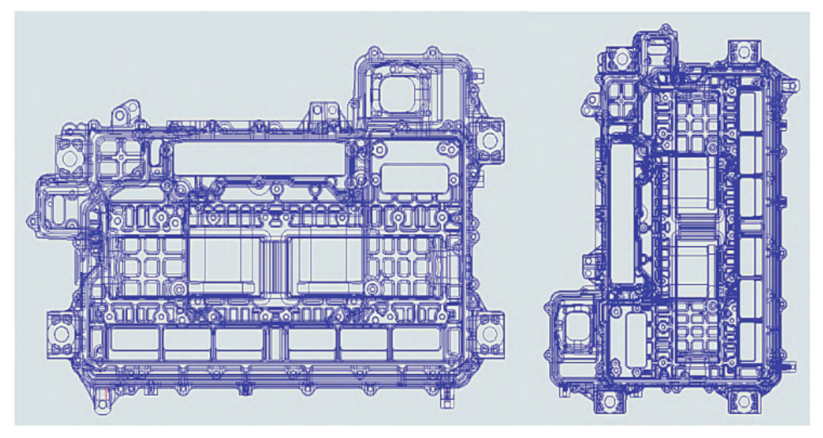
Figure 1 automobile box parts
(1) Positioning surface position confirmation.
Automotive box parts usually high dimensional accuracy, positioning surface generally take 3 fixed support points plus 1 ~ 3 floating support points.
Among them, the location of the three fixed support points of the fixture should be uniform. The center of gravity of the product needs to fall within the triangle formed by the three fixed support points to prevent tilting of the parts during fixture placement.
(2) Positioning hole confirmation.
In the first process, positioning holes are designed into the parts. In the second process, reference holes are used, which have already been processed in the first process. The hole size is generally ideal between 6-10mm, and should be specified according to the dimensions on the drawings.
(3) Confirmation of the clamping position.
The clamping position should ideally be directly above the positioning support points. If it is not aligned, there may be instability in the part size, especially for thin-walled products, where this issue is more noticeable.
Fixture body design
(1) Clamping method and clamping force confirmation.
There are many clamping methods, including manual clamping, automatic clamping and semi-automatic clamping.
Automobile box parts on the precision and efficiency requirements are relatively high, so usually use automatic clamping method.
Automatic clamping is divided into pneumatic and hydraulic types. Pneumatic clamping is cost-effective but less stable, while hydraulic clamping offers high reliability. Considering the precision requirements for automotive box parts, hydraulic clamping is usually preferred.
Commonly used hydraulic clamping cylinder has two kinds: corner cylinder and lever cylinder.
In designing fixtures for automotive box parts, the required total clamping force is typically between 900 and 1300 kgf/cm² (1 kgf/cm² = 98.0665 kPa). Considering the fixture layout and proportional clamping force, 4 to 6 cylinders are usually used.
(2) Design of positioning pins.
Fixture positioning pins play a vital role in machining and assembly. Their main purpose is to ensure the accurate positioning of the component or workpiece in the fixture, ensuring machining accuracy and efficiency.
The primary function of fixture positioning pins is to ensure precise positioning. Through specific design and installation, these pins restrict the object’s movement in two-dimensional space. This ensures that the workpiece or component is fixed in the correct location within the fixture, effectively preventing positional deviations caused by machining errors.
In practice, the positioning holes in automotive box parts are formed by the die-casting mold in the first process. However, changes in the die-casting process and wear of the mold often cause fluctuations in the hole size. If the positioning pin has a fixed diameter, over time, it may no longer fit the varying hole sizes, making accurate positioning difficult.
For this reason, the design of parts of the first process of machining fixture positioning pin in the actual design is usually used in the form of spring pin.
In the second process of designing automotive box parts machining fixtures, the positioning holes have already been precisely machined in the first process. Therefore, standard positioning pins can be used. To facilitate fixture standardization and future maintenance, the positioning pins are not directly attached to the fixture body. Instead, a positioning pin base is designed to serve as a connection carrier between the pins and the fixture.
(3) Design of positioning surface.
Fixed and Floating Support Surfaces
The fixture design for positioning surfaces generally follows the three-point principle. However, given the large size and high precision requirements of automotive box parts, three support points are often inadequate. To address this, the fixture is typically designed with three fixed positioning surfaces and two to five floating supports to ensure accurate and stable positioning.
When dealing with die-casting blanks, the contact area between the fixed positioning surface and the part must be carefully controlled—it should not be too large or too small. Due to size fluctuations inherent in die-cast parts, an excessively large contact area may reduce positioning accuracy, while a small contact area could result in inadequate clamping force, leading to indentation or instability. In practice, the contact area of the positioning surface is usually between 50–120 mm².
Gas Detection and Floating Support Mechanism
To prevent misplacement or improper clamping, modern machine tools often include a gas detection system. This involves a small hole (~1 mm²) on the positioning surface, connected to the machine’s air tube. If the part is missing or placed incorrectly, the hole remains exposed, and the system prevents operation. If the part is properly placed, covering the hole and preventing air leakage, the system allows the machine to run.
Floating supports are typically implemented using hydraulic support cylinders, which come in two types: hydraulic rising and spring rising.
- In the hydraulic rising type, the piston rod starts in a lowered position. When oil pressure is applied, the rod rises to contact the workpiece and stops upon contact. Additional oil pressure applies a clamping force to stabilize the workpiece.
- In the spring rising type, the piston rod is initially raised. When the workpiece is placed, its weight causes the rod to lower slightly. Hydraulic pressure is then applied to secure the rod and provide stable support.
These combined features ensure precision, repeatability, and safety during the machining of complex automotive box components.
(4) Clamp specific design, as shown in Figure 2.
In the automotive box parts fixture design, the clamp is a positioning mechanism, clamping mechanism, pre-positioning and error-proofing, flushing and other institutions of the carrier.
Clamp specific generally installed in the middle of the two L plate, L plate is connected to the clamp specific and turntable tailstock bridge.
For aesthetics and convenience, the clamp will have built-in oil and gas lines.The clamp thickness is designed between 45-55mm.The length and width depend on the product size and the positioning mechanism.
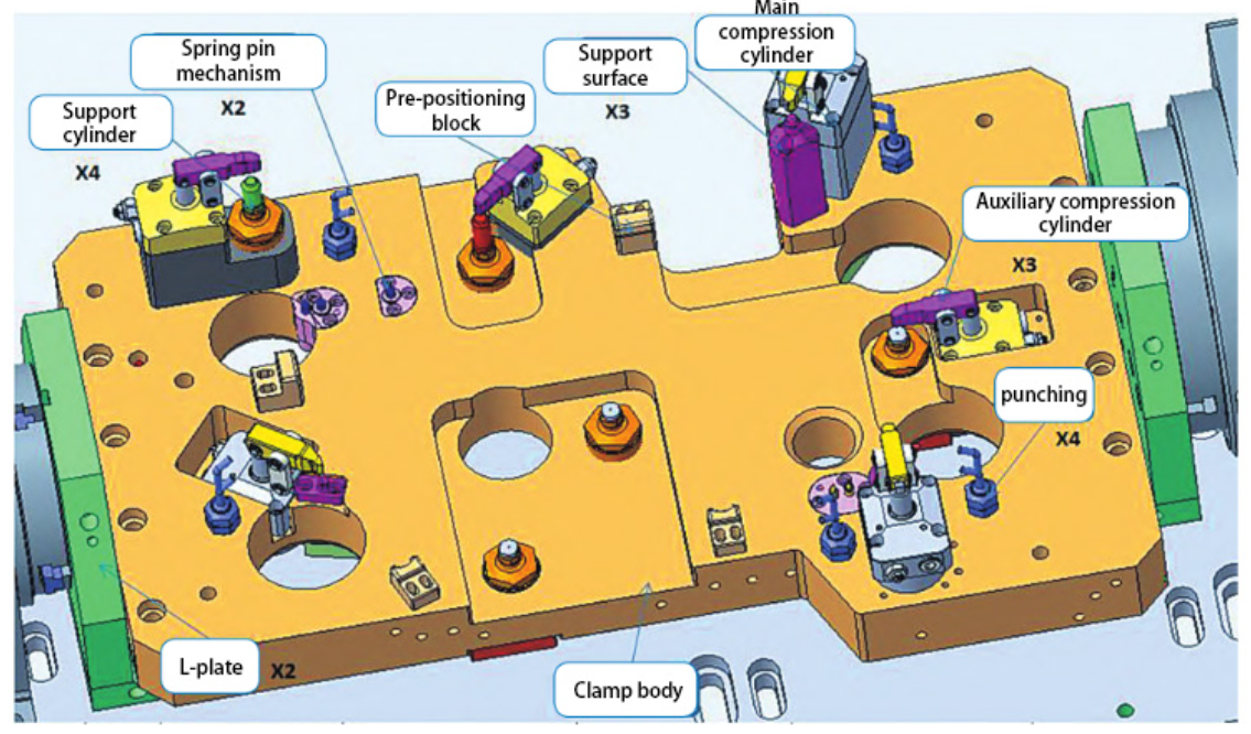
Figure 2 fixture specific schematic
(5) Fixture interference check.
Automotive box parts processing is complex, requiring the use of many tools, such as drilling, milling, and boring. Fixtures must be flipped during the process to clamp parts at different angles for various operations.
Therefore, after the completion of the design of the fixture need to simulate the tool machining process, to see if there is interference, to prevent the fixture on the machine after the knife phenomenon.
Conclusion
With the continuous development of fixtures, functional components on the basis of standardization, special, adjustable and combined fixtures and more micro-small hydraulic devices composed of power clamping system will become the trend.