CNC machining of parts typically involves design modeling, process planning, programming, setup debugging, simulation and verification, tool – setting operation, test – cutting processing, quality control, and formal processing. Among these, the selection and application of the tool method is a crucial part of the process, significantly impacting the machining quality of parts.
In CNC machining, there are two coordinate systems: the machine coordinate system and the workpiece coordinate system. The machine coordinate system is set by the machine tool manufacturer and is based on a fixed reference point—it cannot be changed and is considered a “fixed point.”
Workpiece coordinate system is the CNC programming based on the design of the parts benchmarks for the convenience of programming by the programmer to set the coordinates. Programming convenience set by the programmer’s coordinate system, is variable, is a “moving point”.
When the workpiece is mounted on the machine table, the coordinate values in the program are prepared based on the workpiece coordinate system for programming convenience. However, the CNC system initially only recognizes the machine coordinate system. Therefore, it is necessary to link the two systems. A key method to achieve this link is tool setting. Tool setting determines the coordinate values of the workpiece origin within the machine coordinate system—this is the basic principle behind tool setting.
Using the FANUC-0i CNC milling machine as an example, we can analyze various tool setting methods and their applications. This helps learners and operators accurately, flexibly, and quickly establish the work coordinate system, guiding practical production activities.
Tool setting method analysis
CNC milling machine tool setting method has a variety of different ways, according to the different ways of tool setting, can be divided into the following three categories.
(1) Test cut to the knife method: usually using cutting tools, through the test cut to establish the workpiece coordinate system.
(2) Tool to tool method: the main tools are edge finder (mechanical, photoelectric), Z-axis setter, ruler, mandrel, block gauge, etc., through direct or indirect way to establish the workpiece coordinate system.
(3) Gauge to the tool method: the main percentage or micrometer and other more common gauges to indirectly establish the workpiece coordinate system.
But no matter what kind of tool method, the goal is to directly or indirectly determine the tool position point in the machine coordinate system coordinates.
> Test cutting tool method
(1) Tool
The tool method is generally used in the processing of the first tool end milling cutter, give priority to the use of flat bottom end milling cutter or round nose cutter.
(2) Tool method
The test cut tool method uses the tool to directly cut the workpiece, aligning the tool position point with the origin of the workpiece coordinate system. Alternatively, it can be used to establish the coordinate system by calculating the offset value based on the cutting result.
For example, a blank material specifications for 100mm × 100mm × 30mm, the requirements of the workpiece coordinate system is established in the center of the upper surface of the blank, usually using the centering method for knife.
The main steps are as follows:
1) Determine X0Y0.
1. Mode select MDI mode, enter M03S800 to start the spindle positive rotation;
2. Select handwheel mode and multiplier X100. Move the table and spindle. Quickly position the tool to the left of the workpiece in the safe area, keeping a proper distance.
3. Adjust the handwheel multiplier to X10. Slowly move the tool towards the workpiece. Listen for sounds, observe chips, and center the tool. Once the tool touches the workpiece, set the X – axis value in the relative coordinate system to zero.
4. Lift the tool along the positive Z – axis until it reaches a safe height above the workpiece’s upper surface. Then, use the same approach to make the tool touch the workpiece’s right edge and record the current X – axis value in the relative coordinate system.
5. Retract the tool along the positive Z – axis to a position above the workpiece surface. Then, using the handwheel, move the X – value in the relative coordinate system to X/2.
6. Repeat the same process for the Y – axis and position the tool at Y/2. Then, switch to the offset coordinate system interface, enter the measurements X0 and Y0 in G54. Thus, the X0Y0 tool setting is completed.
2) Determine Z0.
Select handwheel mode and turn the spindle forward. Move the Z – axis to just cut the blank’s upper surface. In the offset coordinate system interface G54 (usually the first of G54 – G59), input Z0 measurement for Z.
The procedure of the test-cutting method is shown in Fig. 1.
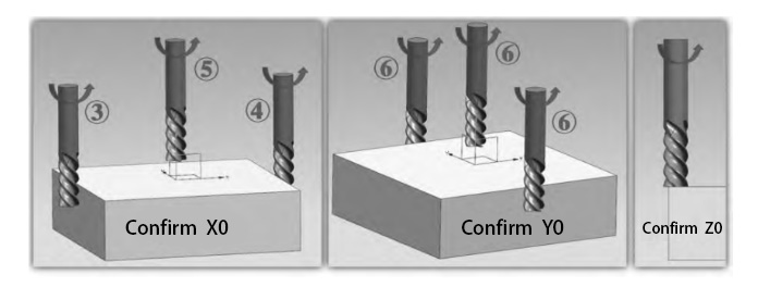
Figure 1 test cutting tool setting process
3) Tool setting analysis
1) This method is easy to operate, but it may leave cutting traces on the workpiece surface, affecting its aesthetics. Additionally, the tool setting accuracy is lower. Therefore, it is suitable for situations where the cutting process does not impact the quality of subsequent machining, offering fast and efficient tool setting.
2) The tool setting method, due to less control over the cutting amount, is known as rough tool setting. If the blank size is sufficient, a ruler can be used to find the center. By moving the tool and observing, it can be placed in the center position, offering a more efficient alternative to centering. However, this method sacrifices some accuracy in tool setting.
3) The centering method requires two touches in the XY direction, which is time-consuming. However, if the length and width of the blank are known, only one side needs to be touched. In G54, enter [X ± (length or width + tool diameter) / 2]. The measurement can be positive or negative to determine the workpiece coordinate system origin. If the touch point is positive, use the negative value; if the touch point is negative, use the positive value.
4) If the upper surface of the blank is usually uneven, the Z0 need to find the lowest point in the upper surface of the blank to prevent the Z value is too high, resulting in the surface of the blank directly into the final machining surface, affecting the processing quality.
Theoretically, the uneven blank surface should be milled flat before tool setting, but this is time-consuming and inefficient. In actual production, a milling cutter can mill in a “cross” pattern to find the lowest point and determine Z0, as illustrated in Figure 2.
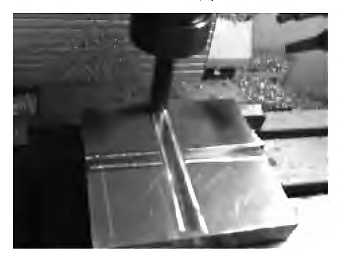
Figure 2 “cross” on Z0
> Tool to tool method
(1) Tool
The test – cut tool – setting method suits rough parts where cutting won’t affect processing quality. For machined parts with an uncuttable appearance, choose the tool – to – tool method. It’s an indirect way using tools like edge finders, Z – axis setters, etc., as shown in Figure 3.
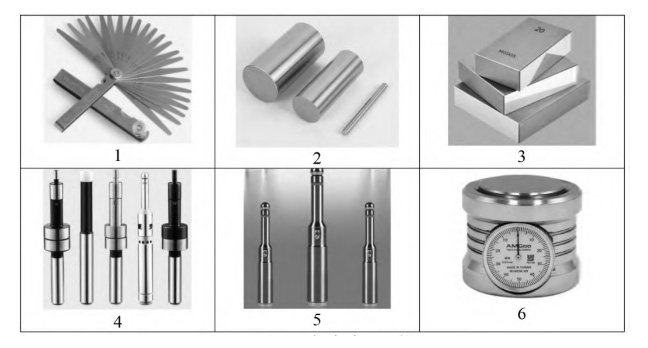
Figure 3 a variety of tools
(2) Tool method
1) Using tools like a plug ruler (or mandrel, block gauge) for tool – setting is similar to the test – cut method. But during tool – setting, keep the spindle stationary.
In the tool and workpiece contact point between the insert ruler (or core rod, block gauge), until the ruler is clamped, can not easily slide until.
When using the tool – setting method, note that in most cases, the size specifications of the plug ruler (or mandrel, block gauge) aren’t needed during tool – setting. But for one – sided tool – setting, carefully calculate these size specifications when determining the workpiece coordinate system.
In this method of tool setting, the spindle does not rotate, so it does not cause any scratches or damage on the surface of the workpiece. Although this method does not leave traces on the surface of the workpiece, but its accuracy is not high.
2) In the field of machining, the use of a mechanical edge finder for tool setting is an efficient method of tool setting. It is mainly used to determine the zero position of the X-axis and Y-axis of the workpiece.
The procedure resembles the test – cut method, but here, an edge finder replaces the tool. Due to its high efficiency and accurate tool – setting ability, this method is widely used in industrial production.
However, it’s important to note that when using an edge finder, the spindle speed generally should not exceed 800r/min. Otherwise, the mechanical edge finder may be damaged during rotation.
3) When using a photoelectric edge finder for tool setting, the workpiece must be a good conductor. This method can only determine the X0 and Y0 coordinates. It requires careful operation, ensuring that the ball lightly touches the workpiece. The reference surface must also have good surface roughness to guarantee tool setting accuracy.
4) The Z-axis setter is used to determine the Z0. First, it must be calibrated. Without rotating the spindle, place the setter on the upper surface of the workpiece. Lower the tool until it just touches the top surface of the setter and the dial pointer reads zero. Then, in the offset coordinate system (e.g., G54), input the Z-coordinate value as Z50—assuming the standard height of the setter is 50mm.
This method is an indirect tool setting method, which is more accurate and easier to operate.
(3) Tool analysis
1) When using a ruler (or standard mandrel, standard block gauge) for tool setting, the following method is commonly used. Set the handwheel multiplier to X10, then turn the frame to move down 0.01 mm. The ruler should not pass through. Afterward, move the frame back to raise the tool by 0.01 mm, allowing the ruler to just pass through. This indicates that the tool is correctly positioned.
2) Tool to tool method can be used alone, can also be used in combination. For example, the mechanical edge finder or photoelectric edge finder (to determine X0Y0) can be used in combination with the plug ruler, standard mandrel, standard block gauge, Z direction setter (to determine Z0).
(3) When using the mechanical edge finder, attention should be paid to the spindle speed, which should generally not exceed 800r/min. To determine when the edge finder just contacts the surface of the workpiece, set the handwheel multiplier to X10 and observe the coaxiality of the upper and lower parts of the edge finder. The upper and lower parts should be coaxial. Continue to move the handwheel by one frame; when the upper and lower parts are exactly misaligned, then return by one frame. At this moment, the edge finder will have made just the right contact with the measurement position.
(4) When using a photoelectric edge finder, it is important to ensure that the material to be processed is conductive. The spindle should not rotate during the process. Additionally, the location of the maximum diameter of the sphere should be touched. If this is not done correctly, it will affect the accuracy of the tool setting.
> Gauge tool method
(1) Tool
This method uses common tools like a percentile or micrometer, which are typically used for cylindrical parts. It can also be applied to rectangular parts, although it may be a bit more troublesome.
For cylindrical parts, the tool setting mainly uses the “three points to determine a circle” principle. By measuring three different points, you can adjust and ensure that the center of the machine tool spindle coincides with the center of the workpiece.
For rectangular parts tool setting, the X or Y-axis ends of the circle are primarily used. The maximum value of the percentage meter is adjusted, supplemented by the relative coordinates zeroing method. The symmetry of the two circles on the workpiece helps determine the workpiece center.
In CNC machining, the tool setting method based on the principle of “three points to determine a circle” ensures the alignment of the machine spindle’s center with the workpiece center. This is done by measuring three different points on the workpiece, allowing for precise adjustment and accurate positioning.
The procedure is similar to the test cut method, but instead of a tool, an edge finder is used to locate these points. This method is commonly used in enterprises, as it improves tool efficiency while ensuring the accuracy needed for processing.
(2) Tool setting method
1) Cylindrical parts to determine the X0Y0
1. will be equipped with a percentage or micrometer magnetic table attached to the spindle sleeve, see Figure 4;
2. Place the micrometer (or percentile) on the upper surface of the cylinder, then manually rotate the spindle to trace a circle. By adjusting the XY axes, align the center of the tool with the center of the workpiece.
3. Repeatedly fine-tune the X and Y-axis positions of the worktable until the pointer of the micrometer remains in the same position during one full rotation of the spindle. The runout of the pointer should be within the allowable tool error range. At this point, the center of the spindle is aligned with the origin of the X and Y axes. For example, Figure 4, point A, and so that the percentage meter has a compression value, such as 0.36mm;
4. Manually rotate the spindle, allowing the micrometer (or percentage meter) probe to move along the circumference of the workpiece surface to point B. At point B, record the value displayed on the micrometer, such as 0.20mm.
5. Slowly move the worktable along the X-axis, so that the percentage meter at point B shows a compression value of 0.20 + (0.36 – 0.20) / 2 = 0.28mm. At this point, the meter value at point B is 0.28mm, and this indicates the center of the workpiece. If the worktable is then rotated to point A, the pressure table value should also read 0.28mm, confirming the alignment of the X and Y axes at the center of the workpiece.
6. Rotate the spindle until the percentage meter needle reaches point C. Adjust the pressure table value to 0.28mm. At this point, the center of the spindle can be considered as the origin of both the X-axis and Y-axis.
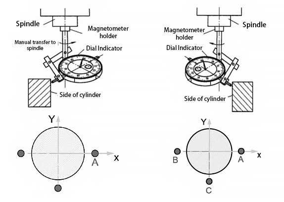
Figure 4 cylindrical parts of the percentage table tool setting method
2) Rectangular parts to determine the X0Y0
1. Will be equipped with a percentage meter or micrometer magnetic table seat attached to the spindle sleeve.
2. Handwheel adjustment X, Y, Z axis, so that the percentage (or micrometer) contacts pressed to the rectangular workpiece in the direction of the X-axis on one side, as shown in Figure 5, point A.
3. Manually rotate the spindle to draw a suitable diameter circle at point A, as shown in Figure 5. Read the maximum value on the percentage meter (or micrometer), for example, 0.50mm, and record this value. Simultaneously, set the corresponding coordinate value to zero.
4. Raise the Z-axis, with the handwheel will be a percentage (or micrometer) to move to the other end of the workpiece point B, the same way to draw a circle of the appropriate diameter, and use the handwheel to adjust to the X-direction position, until the percentage (or micrometer) the maximum reading value of 0.50 mm.
5. Read the relative coordinate value of the X-direction at this time, if the relative coordinate value of X is -130.60mm. Divide -130.60mm by 2 to equal -65.30mm.
Raise the Z-axis, move the X-axis toward the center, and the value of the relative coordinate system will be -65.30. At this time, the center of the main spindle will be the origin of the X-axis of the workpiece.
The same method to find the center of Y direction, and finally switch to the G54 coordinate system interface, input X0 measurement and Y0 measurement, that is, to complete the X0Y0 tool setting.
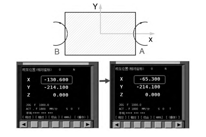
Figure 5 rectangular parts tool setting
3) Tool analysis
1) The use of a percentage gauge or micrometer for tool setting provides high accuracy, but the operation is relatively complex. It requires repeatedly adjusting the pressure gauge value, which results in lower efficiency.
2) In precision machining, such as holes or cylindrical surface finishing, the use of percentile or micrometer tool setting can provide high tool setting accuracy.
However, the operation process of this tool setting method is cumbersome and relatively inefficient. Therefore, in the roughing stage, considering both machining efficiency and ease of operation, this method is generally not recommended.
3) In tool setting, choose a straight line parallel to the X-axis, and the closer the line is to the X-axis, the higher the accuracy of tool setting.
This is because tool setting in the vicinity of the X-axis reduces the deviation caused by machine tool error or improper operation, and thus improves the machining accuracy.
4) When drawing a suitable circle and adjusting the pressure gauge to the correct value, it is important to remember that the table frame and table head should not be moved manually. Adjustments must only be made by moving the X or Y axis. Moving the table frame or head manually can result in completely incorrect tool setting.
Conclusion
The tool setting on a CNC milling machine plays a critical role in ensuring the quality of part processing. Choosing the appropriate and reasonable tooling method not only protects the quality but also significantly enhances production efficiency. In actual production, users should consider the specific production circumstances, follow the guidelines for each tooling method, and carefully select the most suitable option, ensuring flexibility and precision in its application.