CNC lathe occupies a key position in the field of modern machining, which combines high precision and high efficiency characteristics, and is widely used in many parts manufacturing process. However, the task of large depth groove machining is always a difficult problem in this field.
Along with the continuous increase in the depth of the groove, the defects of the traditional machining process become obvious.
The tool rigidity is insufficient, causing frequent vibration and deformation under the action of cutting force.
This seriously jeopardizes the dimensional accuracy and surface quality of the groove. At the same time, chip removal is not effective.
At the same time, poor chip removal triggers chip accumulation, which leads to tool breakage and machining surface scratches and a series of bad conditions, machining accuracy and productivity suffered a great impact.
n view of this, carrying out an in-depth investigation and optimization of the CNC large-depth internal groove machining process undoubtedly has very critical practical value and far-reaching significance.
Such efforts can not only fill the current inadequacies of the processing technology, but also are expected to inject a strong impetus for the high-quality development of the relevant manufacturing industry.
Traditional CNC large depth groove machining process analysis
> Tool selection and use
Under the traditional processing mode, the ordinary internal groove turning tool is widely used because of its simple structure and can adapt to the limitations of the internal groove machining space.
However, in the case of large depth internal groove machining, its inherent disadvantages are exposed.
The small diameter and long length of the toolholder result in a serious lack of overall tool rigidity.
Under the continuous action of strong cutting force, the toolpost is prone to bending deformation, and this deformation is directly transferred to the cutting edge, making it difficult to accurately control the shape and dimensional accuracy of the groove.
For example, when machining internal grooves with a depth of more than 30 mm, the radial runout of the tool may exceed 0.1 mm, which is far beyond the tolerance range allowed for precision machining.
In addition, the geometric parameters of the cutting edge of common internal groove turning tools are often not fully considered at the beginning of the design process.
This is particularly critical when dealing with the special process requirements of large-depth groove machining.
As a result, the cutting force during the machining process becomes unevenly distributed, and its magnitude increases significantly.
This further aggravates the instability of the tool during machining. Consequently, the wear rate of the tool is significantly accelerated. The service life of the tool is therefore greatly shortened.
> Cutting parameter setting
The traditional machining process in the cutting parameters set excessive reliance on empirical judgment, the lack of systematic, scientific optimization analysis means.
In the large depth of internal groove machining scenario, unreasonable cutting speed, feed and depth of cut combination caused many problems.
Excessive cutting speed causes friction between the tool and workpiece. This leads to a sharp rise in temperature. The inner groove space is closed, so heat cannot dissipate quickly. The tool faces the risk of overheating, wear, or burning.
For example, when machining high-strength alloy steel in grooves, if the cutting speed exceeds 150 m/min, the tool edge temperature may quickly rise above 800°C. This causes a sharp decline in tool material hardness. Cutting performance is then seriously impaired.
Too large a feed will significantly increase cutting force. This overloads the tool and accelerates wear. It also reduces machining accuracy. Groove size may deviate and surface roughness may exceed design requirements.
> Cooling and lubrication
The traditional cooling and lubrication methods mostly use external pouring coolant to the cutting area.
In large depth internal groove machining, this method is difficult to ensure coolant reaches the bottom. The coolant often cannot reach the critical cutting position. This greatly reduces cooling and lubrication efficiency.
Due to insufficient cooling and lubrication in the cutting area, the friction coefficient rises significantly. The machined surface quality deteriorates, and surface roughness increases sharply.
At the same time, the high temperature environment leads to a rapid decline in the mechanical properties of the tool material, hardness and toughness reduction, tool life is significantly shortened.
More seriously, chips cannot be flushed away in time and accumulate in the groove. This blocks the processing area and worsens conditions. It increases the risk of tool breakage. In severe cases, the entire machining process may be forced to stop.
> Programming method
Traditional programming in the large depth of internal groove machining is usually a simple linear interpolation way. This programming strategy does not take into account the variation of the cutting forces on the tool at different depths and the chip discharge.
When cutting at the bottom of the groove, the tool experiences a longer extension length and a larger cutting force.
Under these conditions, linear interpolation is likely to cause violent vibration of the tool.
This vibration not only affects machining accuracy, but also increases errors in the cylindricity and straightness of the groove.
In addition, the vibration leaves visible marks on the machined surface. These marks reduce the overall surface quality.
Moreover, the linear interpolation method is not conducive to the orderly discharge of chips, chips are easily entangled in the groove, hindering the subsequent cutting process, increasing the machining risk and reducing the machining efficiency.
Process Improvement Measures
> Optimized tool design
1. Enhance tool rigidity
In order to effectively cope with the problem of insufficient tool rigidity in the machining of large-depth internal grooves, a special large-depth internal groove turning tool with a thickened shank is made.
By increasing the diameter and wall thickness of the toolholder, the overall rigidity and vibration resistance of the tool are significantly improved.
For example, by increasing the shank diameter from the conventional 10 mm to 15 mm and the wall thickness from 2 mm to 3 mm, the radial rigidity of the tool can be increased by approximately 50%.
At the same time, the overall strength of the toolholder is further strengthened. This is done by carefully designing special reinforcement structures inside the toolholder. These include uniformly distributed multiple ribs. High-strength materials, like carbon-fiber-reinforced composites, are used in the hollow filler.
After verification through finite element analysis simulation, it was found that the maximum deformation of the toolpost can be reduced by about 40%. This reduction occurs under the same cutting force. The ribbed plate reinforcement structure is adopted to achieve this.
This structural improvement ensures that the tool maintains a stable cutting state throughout the entire process of machining deep grooves.
It effectively suppresses both vibration and deformation. As a result, it lays a solid foundation for achieving high-precision machining.
2. Optimize cutting edge geometry parameters
According to the unique process characteristics of large depth internal groove machining, the tool’s geometric parameters are finely optimized. The cutting edge angle, back angle, and edge inclination are carefully adjusted.
Appropriately increase the front angle, the value range can be set between 10 ° ~ 15 °, can effectively reduce the degree of plastic deformation of the cut metal layer, thus significantly reducing the cutting force.
For example, when machining large depth internal grooves in aluminum alloy, increasing the front angle from 5° to 12° can reduce the cutting force by about 20% to 25%.
Reasonable adjustment of the back angle, so that it is between 8 ° ~ 12 °, can effectively reduce the friction and wear between the tool and the machined surface.
Carefully set the appropriate camber angle, generally take 3° ~ 8° positive camber angle, to promote the chip can be discharged smoothly, to avoid the accumulation of chips in the front face of the tool.
Through this multi-parameter synergistic optimization, the cutting performance of the tool can be improved, the tool life can be extended and the machining cost can be reduced.
> Cutting parameter optimization
1. Determination of parameters based on cutting simulation
Fully utilize the advanced cutting simulation software (such as AdvantEdge, ThirdWave AdvantEdge, etc.), the large depth of the groove machining process for a comprehensive, in-depth simulation and analysis.
During simulation, the physical properties of the workpiece material are inputted, including hardness, strength, and thermal conductivity. Detailed geometrical parameters of the cutting tool, such as shank size and cutting edge shape, are included. Different combinations of cutting speeds, feeds, and depths of cut are accurately entered.
The cutting force, cutting temperature, tool wear and other important data during the cutting process are accurately obtained through simulation.
Taking the machining of large internal grooves in 45-gauge steel as an example, we set the cutting speed to 80–120 m/min. The feed rate is set in the range of 0.05–0.15 mm/r. The depth of cut is set between 2–5 mm. Multiple sets of simulation experiments are conducted.
According to the simulation results, the effects of different parameter combinations on the machining process were systematically analyzed, and the optimal combination of cutting parameters was selected.
For example, when the cutting speed is 100 m/min and the feed is 0.1 mm/r, the depth of cut is 3 mm. The cutting force is more balanced, and the cutting temperature is controlled within a reasonable range. Tool wear is minimized, keeping the cutting process ideal. Tool wear and machining accuracy are effectively controlled while ensuring machining efficiency.
2. Dynamic adjustment of cutting parameters
In the actual machining process, skillfully with the help of CNC system equipped with high-precision sensor feedback function, real-time, accurate monitoring of cutting force, cutting temperature and other key parameters of the dynamic changes.
According to the monitoring data, the use of intelligent control algorithms to dynamically adjust the cutting speed, feed and other cutting parameters.
For example, when monitoring shows that the cutting force increases by more than 10% of the set threshold, or the cutting temperature rises close to the critical temperature of the tool material, immediate action is taken.
The CNC system then commands a reduction in cutting speed by 10% to 20%. At the same time, the feed rate is reduced by 5% to 10%.
This adjustment effectively prevents tool overloading and overheating.
It also ensures the stability of the machining process and maintains the consistency of machining accuracy.
This dynamic adjustment strategy can optimize the cutting parameters according to the actual machining conditions, significantly improve the machining quality and tool life, reduce the scrap rate.
> Cooling and lubrication system improvement
1. Combination of internal cooling tool and high pressure cooling system
Innovative use of internal cooling type large depth internal groove turning tool, carefully designed and processed coolant channel inside the shank, to ensure that the coolant can be directly and accurately sprayed to the cutting edge parts.
At the same time, a high-pressure cooling system is equipped to deliver the coolant to the internal channels of the tool at a high pressure of 5 ~ 10 MPa.
During the machining process, the coolant breaks through the high-temperature and high-pressure barrier in the cutting area. It reaches the bottom of the groove and other critical locations. These areas are difficult to reach by traditional cooling methods.
For example, in the machining depth of 40 mm internal groove, high-pressure coolant can effectively reduce the temperature of the cutting area of about 30% ~ 40%, significantly improve tool life, reduce the frequency of tool replacement.
Moreover, the powerful flushing force of high-pressure coolant can quickly wash chips away from the cutting area. It effectively improves chip removal conditions and avoids chip blockage in the groove. This further enhances machining stability and machining quality.
2. Selection of high-performance cooling lubricant
According to the large depth of internal groove machining of specific materials and process requirements, carefully selected with excellent lubricating properties, cooling performance and anti-wear performance of the cooling lubricant.
For the machining of high-strength alloy steel, titanium alloys and other difficult to machine the inner groove of the material, priority is given to the use of cutting oil or emulsion containing sulfur, phosphorus, chlorine and other special additives.
These additives in the cutting process with the tool and workpiece surface chemical reaction, the formation of a layer of strong and low coefficient of friction of the protective film, effectively reducing friction and wear.
For example, in the machining of titanium alloy internal groove, the use of cutting oil containing sulfur additives, tool wear rate can be reduced by about 30% ~ 40%.
At the same time, this type of cooling lubricant has a good cooling effect. It can quickly take away the cutting heat. It reduces the temperature of the cutting area. It promotes the smooth discharge of chips. It significantly improves surface quality and processing efficiency.
> Programming strategy innovation
1. Adopting spiral tool path programming
The spiral tool path is carefully designed to replace the traditional linear interpolation.
The uniqueness of the spiral tool path lies in its ability to guide the tool to gradually cut into the workpiece along a spiral trajectory during the cutting process.
This allows for a uniform distribution of the cutting force. It effectively avoids the tool being subjected to excessive concentration of cutting force at any particular location.
As a result, the risk of tool vibration and deformation is significantly reduced.
For example, when machining an internal groove with a depth of 35 mm, the spiral toolpath programming is used. Compared with the linear interpolation method, the maximum vibration amplitude of the tool can be reduced. The reduction is about 60% to 70%.
At the same time, the spiral groove formed by the helical toolpath provides a smooth discharge channel for the chips.
The chips can be discharged from the groove in an orderly manner along the spiral path.
This effectively prevents chip accumulation and entanglement within the groove. As a result, the stability of the machining process and the overall machining quality are greatly improved.
It also ensures that the surface roughness and dimensional accuracy of the groove meet the requirements of high-precision machining.
2. Layered cutting programming
According to the depth direction of the large depth groove for scientific and reasonable layer programming processing.
According to the change rule of groove depth, each layer of cutting adopts differentiated cutting parameters.
In the initial stage of the groove depth is shallow, make full use of the advantages of good tool rigidity, the use of larger cutting parameters to improve machining efficiency.
For example, when the groove depth is less than 10 mm, the cutting speed is set to 120 m/min, the feed is set to 0.12 mm/r, and the cutting depth is set to 3 mm.
As the groove depth increases, tool rigidity decreases and cutting force rises. Cutting parameters are then gradually reduced to adapt to these mechanical changes during machining.
For example, when the groove depth reaches 30 mm, the cutting speed is adjusted to 80 m / min, the feed is reduced to 0.08 mm / r, and the cutting depth is reduced to 2 mm.
Through this layered cutting programming strategy, the tool force at different depths can be accurately controlled. It effectively improves machining accuracy and extends tool life. It also reduces machining costs and balances efficiency with quality.
Actual processing case verification
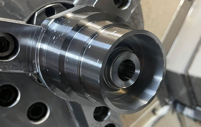
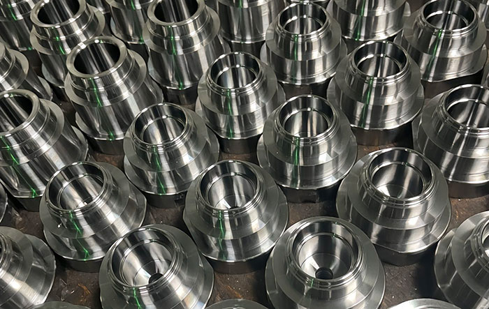
To a particular material (such as 40Cr alloy steel) shaft parts groove machining, for example, the depth of the groove reached 50 mm, undoubtedly belongs to the challenging depth of the groove machining category.
A series of problems were encountered during conventional groove machining. Frequent tool breakage occurred during the process. Machining an inner groove with a depth of 50 mm is very challenging.
Frequent tool breakage occurred during machining. Surface roughness was extremely poor, reaching up to Ra 6.3. Groove dimensions seriously exceeded accuracy, with a tolerance band up to ±0.15 mm. Machining efficiency was extremely low. Average machining time reached up to 3 hours per piece.
In order to solve the above problems, the above improved processing technology was adopted decisively. First of all, the special large-depth internal groove turning tool with carefully optimized design is used.
The thicker shank and optimized cutting edge geometry effectively improve the rigidity and cutting performance of the tool.
The initial cutting parameters are accurately set according to the cutting simulation results and dynamically adjusted in the machining process with the help of the sensor feedback function of the CNC system.
At the same time, the advanced cooling and lubrication method uses internal cooling tools and a high-pressure system. The coolant is sprayed precisely to the cutting area under high pressure. This effectively reduces cutting temperature and improves chip removal conditions.
The use of high performance cooling lubricant with special additives further reduces the friction and wear between the tool and the workpiece.
In addition, the use of spiral tool travel and layered cutting programming strategy, so that the tool cutting process is more stable and the chip discharge is more smooth.
After the actual machining verification, the improved process has achieved remarkable results. The phenomenon of tool breakage has been effectively controlled.
The roughness of the machining surface has been significantly improved, reaching Ra 1.6. The accuracy of groove dimensions has been precisely controlled within ±0.03 mm.
Machining efficiency has been greatly improved.As a result, the machining time for each piece has been shortened to 1.2 hours.
This successful case has fully proved that the improved process has made the machining process smoother and the chip discharge smoother.
This successful case fully proves the improved process is highly effective and reliable. It solves the problem of large-depth internal groove machining. It also provides a valuable practical example for similar CNC turning work. This offers an important technical reference for future internal groove machining.
Conclusion
Through the CNC turning large-depth groove machining process, comprehensive improvements have been made from multiple dimensions.
These include tool optimization, adjustment of cutting parameters, enhancement of cooling and lubrication systems, and innovation in programming strategies.
This all-round, in-depth research and practical improvement have effectively and efficiently solved several thorny issues found in traditional machining processes.
These issues include insufficient tool rigidity, poor chip removal, and difficulties in ensuring machining accuracy.
The strong verification of actual machining cases shows that these improvement measures are effective. They significantly improve the machining quality of large-depth internal grooves. They also enhance the efficiency and stability of the machining process. These improvements provide solid technical support for similar CNC turning operations. They also offer rich and valuable practical experience for internal groove machining.
In the continuous development of machining technology in the future, it should be more closely integrated with the emerging trends of new materials, new technologies, and innovative techniques.
Ongoing efforts are needed to explore more efficient, high-precision, and intelligent methods for deep groove machining.
These new methods and modes should aim to fully meet the increasing demands for high-quality and high-performance parts and components in the industrial manufacturing sector.
Such advancements will vigorously promote the machinery manufacturing industry toward a higher level of progress.
The new method and new mode of large-depth internal groove machining is to fully meet the demanding needs of high-quality and high-performance parts in the growing industrial manufacturing field, and strongly promote the machinery manufacturing industry to a higher level.