Method Design
1.1 Error Control Framework and Digital Twin Model Development
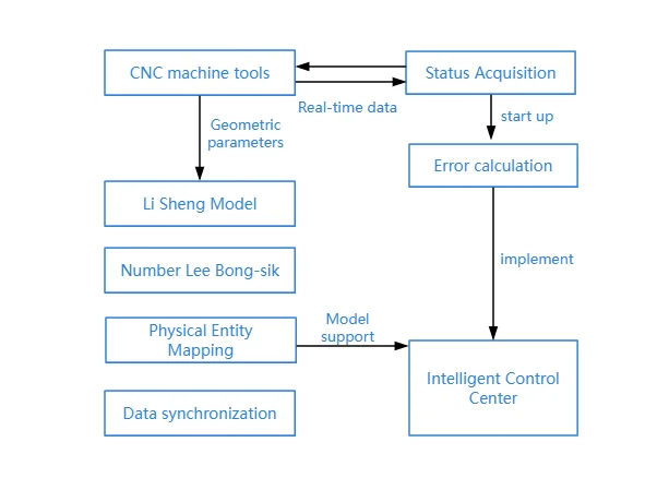
1.1.1 Step 1: Establishing Data Fusion and Interaction Mechanisms
The system uses a unified data acquisition interface to collect real-time data from sensors. These sensors include displacement sensors, encoders, force sensors, and thermal sensors. The system applies timestamp technology to synchronize the data from different sources. Then it transmits the synchronized data to the digital twin computation platform for further processing and analysis.
1.1.2 Step 2: Constructing the Digital Twin
Geometric Model
Engineers use 3D modeling software to create models of each CNC machine component. They base the models on the actual size and structure of the components. They use geometric entities and Boolean operations to build the parts. Then they define assembly relationships and apply constraints to accurately describe the relative positions and motions of the parts.
Kinematic Model
Engineers establish both the machine coordinate system and the tool coordinate system. They use the machine origin as the reference point. They then apply the Denavit-Hartenberg (D-H) parameter method to describe the kinematic relationships between the machine’s axes.
1.1.3 Step 3: Model Mapping and Coupling
Geometric Model Mapping
Technicians set identification points on key machine components. They use a visual measurement system to capture the coordinates of these points in both real and virtual spaces. This process allows them to align the physical and digital models accurately.
Model Coupling
The kinematic model provides input to the dynamic model. The dynamic model calculates the forces that act on the system. These forces cause deformation in the physical model. Changes in stiffness in the physical model then affect the accuracy of the kinematic model. This loop forms a collaborative simulation that allows real-time interaction between all models.
1.1.4 Step 4: Model Synchronization and Real-Time Updating
As the CNC machine operates, it encounters different working conditions. The system collects real-time data during operation. It uses this data to update the digital twin continuously. The digital model adjusts its internal parameters and status based on the latest data. This ensures that the digital twin stays synchronized with the actual machine at all times.
2Experiment and Results Analysis
Researchers designed an experiment to test the contour error control method using a digital twin. They used a five-axis CNC machine tool. The machine had the following specifications:
Axis travel: X = 800 mm, Y = 650 mm, Z = 500 mm
Spindle speed: 20,000 rpm
Rapid traverse rate: 36,000 mm/min
Repeatability: ±0.005 mm
Cutting tool: 10 mm carbide end mill
CNC system: Siemens 840D with motion control and interpolation functions
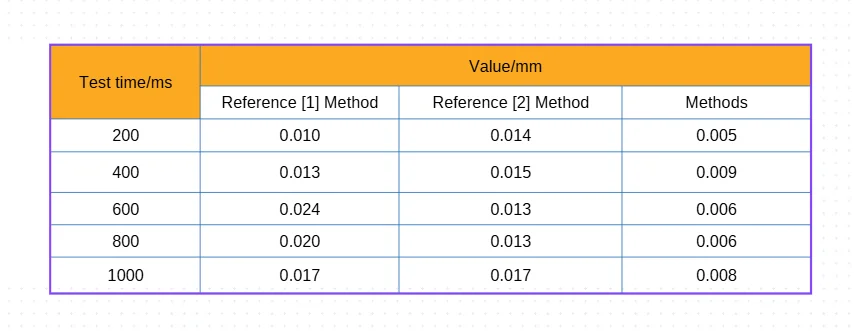
The experiment confirmed the effectiveness of digital twin feedback. It showed that the system could improve contour accuracy during high-speed, multi-axis machining.
3 Conclusion
This study introduces a new contour error control method for CNC machine tools. The method uses digital twin technology to synchronize the machine’s physical attributes, operating conditions, and process parameters with its virtual model. The synchronization occurs in real time. This setup allows the system to calculate errors accurately and apply dynamic compensation.
Compared to traditional methods, this approach significantly reduces the standard deviation of contour errors. It provides a reliable and effective solution for achieving ultra-high-precision machining in modern CNC systems.