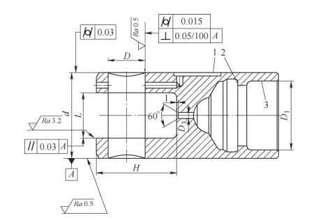
1.Technical Requirements
The tappet in a certain diesel engine uses low-carbon alloy steel. After manufacturing, we carburize and quench the material to reach a hardness of 60–63 HRC. We require an outer diameter tolerance of 0.03 mm, a surface roughness of Ra = 0.5 μm, and cylindricity of 0.03 mm. To meet these specifications, we perform fine grinding using a cylindrical grinder. The roller pin hole and roller groove also have strict geometric tolerances. Therefore, we must precisely machine the outer diameter.
2.Difficulty Analysis
This part has a complex and thin-walled structure. One end includes a roller groove and a roller pin hole. The groove has a depth-to-width ratio of 1.8:1, which gives the part poor rigidity and makes it prone to deformation. The other end contains a blind hole with a thin wall. When we clamp this part, the stress often causes deformation. Because of this structure, we cannot use a process chuck during external cylindrical grinding. We must solve the problem of how to rotate the part using only the machine tool.
3.Fixture Design
Based on the part’s shape and technical demands, we tested two fixture schemes for cylindrical grinding.
3.1 Option 1
We used the MG1432 cylindrical grinder. We designed a fixture that positions the part using two centers. We clamped the part with an expandable mandrel. This setup ensures we finish the seam and outer diameter to the correct size. On the roller pin hole end, we inserted a locating pin into the hole. Then, we clamped the part with a tie rod and machined the center hole. We adjusted the setup to keep the outer diameter runout within 0.05 mm.
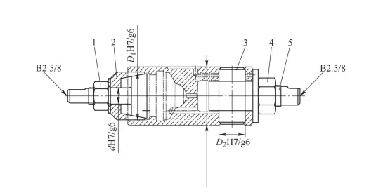
3.2 Option 2
We again used the MG1432 cylindrical grinder and positioned the part with two centers. We used a locating spindle in coordination with a stop to perform high-precision machining of the stop to an H7 tolerance. We also used a hook-shaped pressure plate and an extended center to assist with positioning and chamfering. This setup ensured high accuracy and coaxiality during cylindrical grinding.
4.Effect Verification
We tested both solutions through actual machining.
In Solution 1, we had to align the part’s outer surface before machining. After pressing the roller groove end, clamping often caused deformation. We needed to realign the part several times. After removing the fixture, we observed further deformation. As a result, only 68% of the parts passed inspection. Each part took 30 minutes to process.
In Solution 2, we installed the fixture quickly and easily. The clamping force was light. We didn’t need to align the part before machining. After processing, the parts showed no clamping deformation. The qualification rate reached 95%. Only 5% of the parts were out of tolerance, and none were caused by deformation. Each part took only 15 minutes to process.
The comparison shows that Solution 2 produced less deformation, higher qualification rates, and greater efficiency. This makes it better suited for mass production.
5.Conclusion
In this study, we focused on fixture design for fine grinding the outer surfaces of thin-walled precision parts like diesel engine tappets. We identified common problems such as deformation and clamping difficulty. We proposed two solutions based on standard machining equipment. Our optimized fixture improved both machining quality and efficiency. This work provides useful insights for designing fixtures for similar parts. It has strong value for further application and promotion.