Turn-mill composite machining centers can complete turning and milling operations in one setup, reducing clamping and processes, improving efficiency and accuracy, and are widely used in modern machining.
Turning and milling complex machining centers have a complex structure with many axes. Collisions or abnormal external forces can greatly affect the equipment’s geometric accuracy. This may cause deviation in the concentricity of the main and sub-spindles and, in severe cases, lead to a complete loss of geometric accuracy.
In the past, professional engineers were needed to make adjustments. This process was both time-consuming and labor-intensive. Through experience, some practical skills were developed. These skills helped reduce adjustment time and labor intensity, ensuring smooth progress in machining production.
EMCO mill-turn machining center
The work area of EMCO’s HYPERTURN65 milling center is shown in Figure 1. It features dual spindles, a lower turret on one side, and a high-speed milling axis. Both the turret and milling axis are driven by linear axes. The machine includes multiple axes, offering high flexibility and precision.
The main spindle and sub-spindle require high precision in speed control and angular positioning. During operation, the main spindle, sub-spindle, high-speed milling spindle, and lower turret work in linkage. This complex structure demands precise adjustment of the machine tool’s accuracy.
During use, a coordinate system calculation error by the operator caused a collision. Although no mechanical damage was found, the main spindle and sub-spindle showed significant changes in concentricity and parallelism. Measurements revealed serious deviations of about 1 mm.
We contacted the manufacturer’s engineers for support. At the same time, we explored solutions independently. Eventually, we completed the adjustment and restored the machine tool’s accuracy.
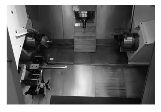
Figure 1 EMCO 65 type mill-turn machining center working area
EMCO compound machining center accuracy adjustment method
Multi-axis adjustment first requires determining a reference axis. After adjusting this reference axis, it is used as the basis to adjust the accuracy of the other axes in a proper sequence.
Select the milling axis (Z-axis) as the reference axis, in accordance with the main axis – sub-spindle – milling axis – turret order for adjustment.
1.Accuracy testing and adjustment of main spindle and sub-spindle
The accuracy testing of main spindle and sub-spindle mainly involves radial runout, axial saving, end runout and other items. When testing, first clean the spindle bore, end face, the use of micrometers for measurement.
Measurement of the micrometer attached to the milling axis, the head of the table pressed on the spindle bore, rotate the spindle by hand, detection of spindle radial runout. The detection of spindle runout adopts the testing method of calibration rod and steel ball.
The steel ball is placed in the taper hole at the shaft end of the calibration rod. The micrometer is then pressed against the steel ball. By rotating the spindle, its shaft runout can be detected. The end runout is measured by rotating the spindle and checking the end face with the micrometer (Fig. 2).
Through the test to verify that the above accuracy of the spindle in the error allowable range.
After that, the spindle is equipped with calibration rods to detect the upper busbar, side busbar and distal runout. The test results show the distal runout is within 0.01 mm. However, the accuracy of the upper and side busbars deviates significantly and requires adjustment.
Measurement of the coaxiality of the main spindle and the sub-spindle was carried out after completing the adjustment of the accuracy of the main spindle.
Due to the collision, the spindle and sub-spindle suffer from impact forces. This alters their concentricity. To ensure accurate coaxial alignment, the main spindle must be used as the benchmark during adjustment.
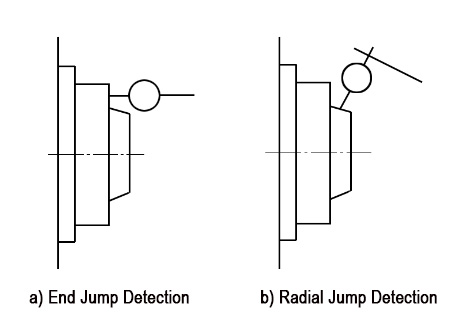
Figure 2 spindle end jump diameter jump detection schematic
During spindle accuracy adjustment, first loosen the spindle seat compression screw. Do not fully loosen it—just turn it half a turn counterclockwise to keep some pressure.
First, adjust the vertical direction perpendicular to the spindle’s horizontal axis. Since the busbar measurement error is 0.04/300 mm, which is large, precise adjustment cannot be achieved by just tightening the compression screw.
We used a copper pad method by inserting a 0.01 mm copper shim at the spindle end. Then, by tightening the compression screw and repeatedly checking the busbar with the rod, we adjusted the precision to within 0.01/300 mm.
After completing the adjustment of the upper busbar, it is necessary to adjust the accuracy of the side busbar. According to the measured deviation of the side busbar, it can be adjusted by adjusting the adjusting screw in the horizontal direction, and fine-tuning by repeatedly pulling the side busbar of the calibration bar until the accuracy of the side busbar is within 0.01/300 mm.
After completing the adjustment of spindle accuracy, it is necessary to adjust the coaxiality of spindle and sub-spindle. The adjustment method is to clamp the long meter rod on the spindle and use a micrometer pressed against the sub-spindle’s inner hole. Rotate the spindle to measure the concentricity deviation between the spindle and sub-spindle. Adjust the screws through repeated measurements until the concentricity falls within the allowable error range. Finally, lock the fastening screws to complete the adjustment.
2.Milling axis precision adjustment
The main test for the milling axis is to check the parallelism between the milling axis and the X-axis. Use an HSK63 mandrel as the calibration rod and attach a micrometer to the spindle. Measure the side busbar of the mandrel and observe the micrometer’s reading deviation as the mandrel moves along the X-axis from top to bottom.
The measurement result shows that the milling axis deviation from parallelism with the X-axis is within the allowable error range. If adjustment is needed, loosen the milling axis fastening screws and gently tap with a wooden hammer to create vibration. Repeat adjustments and measurements until the milling axis parallelism with the X-axis meets the permitted error range.
After the adjustment, tighten the fastening screws, and test again after tightening the fastening screws to make sure that the fastening process does not affect the accuracy.
3.Lower turret accuracy adjustment
After the collision of HYPERTURN65 mill-turn machining center, the accuracy of the center of the lower turret will change greatly. Remove the end cover of the turret end face, attach the micrometer to the milling axis, press the needle in the center of the turret fixed hole, rotate the turret to measure the turret’s center deviation, and find that the center deviation reaches 1 mm, which are all from the gap of the fixing screws.
To adjust the turret disk center deviation, first loosen the center fastening screws. Use a wooden hammer to gently tap and adjust the turret center. Repeat the process of measuring and tapping until the turret disk center accuracy is within 0.015 mm. Finally, tighten the fastening screws to complete the turret disk adjustment.
Thus, the precision adjustment of all axes of the mill-turn machining center is completed.
Adjustment of perpendicularity of X/Y axis of JOBS Gantry Milling Machine
The JOBS gantry milling machine, imported in 2002, is equipped with a Siemens 840D CNC system. It uses a fixed table and moving gantry motion mode. The machine has a gantry frame structure, with the crossbeam and columns bolted together. The gantry crossbeam is designed as a split structure.
During use, forces cause the columns on both sides to move unevenly, leading to deviation in the perpendicularity between the X and Y axes. Over time, these deviations accumulate, reducing the geometric accuracy of the JOBS gantry milling machine and impacting machining precision.
The machine’s X-axis uses servo control with dual screws, dual motors, and dual scale feedback. The system links the X-axis so that the X1 and X2 axes cannot move independently.
It is found that by changing the parameters to release the X-axis linkage, the previous X/Y-axis perpendicularity adjustment scheme is greatly simplified, and the adjustment efficiency is greatly improved while reducing the risk.
1.Adjustment method before improvement
When accuracy problems occurred on JOBS Gantry Milling Machine in the past, a square ruler was first used to measure the perpendicularity accuracy between X/Y axes, and the X1/X2 axes were adjusted on the basis of this accuracy. The adjustment program is;
Loosen the connecting screws between the columns on both sides and the gantry crossbeam to return the X-axis to zero, and use the zero point of the X-axis of the machine tool as an adjusting tool to level the movement deviation of the X1/X2-axis.
The whole adjustment process is time-consuming and laborious, and there is a risk of flying zero.
In order to solve this problem, after consulting and researching from various sources, the X1/X2 axes are unbound by changing the axis parameters, realizing separate control of the X1/X2 axes, which effectively simplifies the adjustment scheme and improves the work efficiency while reducing the work intensity.
2.Improved adjustment program
Firstly, use the square ruler to measure the verticality of X/Y-axis, then loosen the connecting screws between the columns and beams on both sides of the gantry, and change the axis parameter “37100 GANTRY_AXIS_TYPE” to “0” to complete the unlocking of X1/X2-axis, so that X1/X2-axis can be controlled separately. Unlock the X1/X2 axes so that the X1/X2 axes can be controlled individually. Control the movement of the X1 and X2 axes based on the X/Y axis perpendicularity deviation measured with the square ruler. Repeat this process several times until the perpendicularity deviation is eliminated.
Once this is done, re-lock the screws and change the parameters and restart the machine.
Compared to the adjustment scheme used in the past, the new scheme can level the vertical deviation by fine-tuning, which reduces the risk and improves the efficiency.
3.Accuracy adjustment effect
After completing the X/Y-axis perpendicularity adjustment, the perpendicularity reached 0.005/400 mm using a 400×400 square ruler. The machine’s machining accuracy meets usage requirements, and the excessive load issue on the X1/X2-axis motors caused by X/Y-axis misalignment is resolved.
Conclusion
Geometric accuracy adjustment of CNC equipment significantly affects machining precision. For mill-turn composite machining centers, especially imported ones with many axes and high precision, the adjustment process is complex, demanding, and cumbersome.
JOBS gantry milling machine is a large-scale machining equipment, its span and weight are large, the adjustment requirements are also very high. In the adjustment process of mill-turn machining centers, it is important to consult the manufacturer’s engineers and combine the characteristics of the equipment to reasonably arrange the order and method of precision adjustment to improve the adjustment efficiency and ensure the adjustment precision of the equipment.
The previous adjustment program for the gantry milling machine was time-consuming and labor-intensive. By optimizing the program, the adjustment time and manpower were greatly reduced, improving equipment utilization and ensuring the production schedule.