With the continuous advancement in production and processing technologies within the automotive manufacturing industry, the machining quality of crankshaft components in car engines is also steadily improving.
Crankshaft components play a crucial role in the structure and performance of automotive engines. They are also one of the key technical challenges in automotive manufacturing.
Crankshafts are rotating components within an engine and pose significant technical challenges during production. These challenges directly impact engine lifespan, efficiency, and driving safety.
Therefore, ensuring reliable crankshaft quality, improving machining precision, and reducing scrap rates caused by errors and processing limitations is essential for enhancing production efficiency.
This process is vital to the automotive manufacturing industry. It helps improve engine output and ensures operational stability in real-world use.
Working Principle of the Automotive Engine
A car’s structure is composed of numerous critical components, such as the motor, tires, and chassis, all working together to maintain vehicle performance and safety.
The chassis plays a foundational role in a vehicle. It bears the overall load and ensures stable performance during operation. As such, it forms the structural backbone of the entire vehicle.
The motor functions as the car’s power core, and its performance is directly influenced by the coordination and reliability of all other vehicle components.
The quality and efficiency of the motor directly affect a vehicle’s power and safety. This is why internal combustion engines usually operate through four strokes:
① Intake phase:
The crankshaft drives piston movement, which increases the cylinder volume. As the piston moves, air is drawn in. Pressure rises, and air continues entering the cylinder until the piston reaches the bottom.
Throughout the intake process, the temperature of the gaseous medium inside the cylinder gradually increases, preparing the system for compression.
② Compression phase:
As the piston moves upward, both the intake and exhaust valves close; the cylinder volume decreases, and the gas inside is tightly compressed.
③ Power phase:
The spark plug ignites the compressed air-fuel mixture. This ignition creates combustible gas that expands rapidly. The expanding gas drives the piston downward with force.
④ Exhaust phase:
After combustion, the exhaust valves open. The crankshaft then moves the piston upward again. This motion pushes burnt gases out of the cylinder and completes the cycle.
Crankshaft Mechanism and Its Manufacturing Characteristics in Car Engines
1.Structure and Function of the Automotive Engine Crankshaft
The crankshaft is a key engine component in automobiles. It converts the pistons’ linear motion into rotary torque.
This rotary torque is then transmitted through the clutch, flywheel, and drivetrain system to deliver mechanical power for vehicle propulsion and engine operation.
The crankshaft mechanism includes multiple crank throws, and each crank throw is composed of two crank arms, two crankpins, and one connecting rod journal (see Figure 1 for reference).
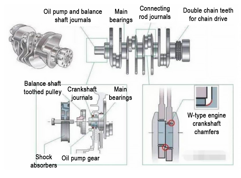
Figure 1 Schematic diagram of automobile crankshaft structure
Inertia and torque forces act on the crankshaft. Internal combustion pressure also affects it. Due to these forces, the crankshaft can wear during continuous rotation.
To ensure reliable crankshaft function and long service life, it is essential to reduce wear. Improving manufacturing quality and part durability is also important. Effective lubrication must be applied as well.
These efforts directly contribute to extending the crankshaft’s operational life and maintaining the engine’s stable and efficient performance over time.
2.Key Manufacturing Features of Automotive Engine Crankshafts
When analyzing the manufacturing process of automotive engine crankshafts, several critical technical features and challenges must be addressed during production.
Firstly, the crankshaft manufacturing process adheres to strict technical standards and precise quality requirements to meet high-performance automotive engineering expectations.
Unlike standard mechanical components, crankshaft parts typically involve multiple machining surfaces with varying dimensions, shapes, and spatial orientations, requiring strict tolerance control.
The machining process must account for dimensional, positional, and shape accuracy, with special attention paid to dividing rough and fine machining stages to ensure overall precision and reliability.
Secondly, crankshaft rigidity is often compromised due to the high length-to-diameter ratio of the component, which can lead to deformation during processing and operation.
To mitigate these rigidity issues, production engineers must ensure sufficient rigidity of fixtures and cutting tools, especially during rough machining, to avoid displacement and imbalance.
Optimized cutting force distribution is also necessary to counteract potential deformation and ensure accurate part geometry throughout the machining process.
Thirdly, the crankshaft’s complex geometry poses unique challenges. This is especially true because of the eccentric distance between the main journals and connecting rod journals.
High-precision control of eccentricity is crucial. The presence of counterweights adds complexity, increasing demands on fixture design and machining accuracy.
Failure to maintain tight geometric tolerances harms crankshaft balance and machining quality. This can cause performance problems in the final engine system.
Crankshaft Machining Technology
1.Crankshaft Blank Machining
In the processing of crankshaft blanks, two main methods are commonly employed in the automotive manufacturing industry, namely casting and forging techniques, depending on the material used.
Manufacturers typically select carbon alloy steel or medium carbon steel for forging. These materials offer durability and strength under mechanical stress.
For casting, spheroidal graphite cast iron, cast steel, and alloy cast iron are commonly used. Each provides different benefits based on application needs.
Comparatively, spheroidal graphite cast iron exhibits more favorable mechanical properties similar to carbon steel, while offering lower material costs, making it widely accepted.
Due to its cost-effectiveness and satisfactory performance, spheroidal graphite cast iron has gained wide application in many enterprises engaged in mass crankshaft production.
2.Rough Machining of Crankshaft Components
When performing rough machining of automotive engine crankshafts, a variety of machining techniques are utilized to meet the demands of high-precision industrial production.
These techniques include turn-broach machining, composite rough machining, external milling technology, and internal milling technology, each chosen based on specific component needs.
In practical machining, selecting the most appropriate technique according to the actual size and structural characteristics of the crankshaft component is essential for efficiency.
Such technical selection can effectively reduce cutting deformation, improve machining accuracy, and ultimately ensure high-quality crankshaft manufacturing.
Technicians using rough machining must ensure precision. For material allowances over 5 mm, external or internal milling is preferred.
When the allowance is within 3 mm, the turn-broach technique is more suitable, offering better control over precision for light-material removal processes.
Moreover, the selection of the appropriate rough machining method should also be based on the crankshaft’s overall length and structural design.
The crankshaft length is about 700 mm. In this case, connecting rod journal machining is usually the best choice. It ensures stability and accuracy during processing.
Throughout the rough machining process, technicians must identify and manage sources of machining deformation and implement quality control strategies accordingly.
Connecting rod journal rough machining helps prevent common deformation problems. The turn-broach technique, however, needs precise parameter control to ensure reliability.
3.Finish Machining of Crankshaft Components
Finish machining is essential in modern automotive engine crankshaft production. It ensures high precision and smooth surface quality on critical areas.
Finish machining technology has rapidly advanced in recent years. Increased automation greatly improves manufacturing efficiency and product consistency.
Historically, many crankshaft components were machined manually using hand-operated crankshaft grinding machines, which presented issues in achieving consistent dimensional precision.
These traditional methods often resulted in unacceptable levels of error and inconsistency, making them unsuitable for today’s high-standard engine production requirements.
Modern CNC-based finish machining technologies enable highly accurate processing while integrating automated operations to improve production speed and reduce labor intensity.
Although CNC equipment is widely applied in crankshaft processing, it often requires significant floor space and does not always translate into significantly higher production rates.
To overcome these limitations, surface smoothness of the crankshaft journal can be optimized using CNC polishing machines, enhancing the finish while ensuring tight tolerances.
This approach addresses the shortcomings of CNC machining alone, allowing the construction of a stable and efficient machining system suitable for crankshaft production.
By implementing CNC polishing solutions, manufacturers can ensure optimal machining density, accuracy, and surface finish, improving both processing reliability and industrial competitiveness.
4.Milling the Two End Faces and Machining the Center Hole of the Crankshaft
When drilling and milling the two end faces of the crankshaft, a specialized drilling and milling machine is used to perform these tasks with precision and consistency.
The goal of this process is to control the crankshaft’s length and accurately locate the center holes, ensuring that both end faces are flat and structurally balanced.
Accurate machining of the crankshaft’s end faces ensures even force distribution during engine operation. This is critical for long-term mechanical stability and performance (see Figure 2).
During the drilling and milling stage, operators should first machine the end faces and then proceed to drill the center holes for the best alignment and surface quality.
The accuracy of center hole machining has a direct impact on the overall quality of the crankshaft and even affects the final precision of subsequent machining operations.
Before drilling center holes, technicians must pay close attention to the operational functionality of the equipment and confirm that all settings meet precision requirements.
At the same time, surface quality inspection of the crankshaft blank is essential to prevent any surface defects from interfering with hole location accuracy or tool path stability.
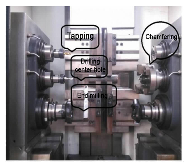
Figure 2. Milling the crankshaft’s end faces and drilling the center hole process
5.Spindle journal Turning
During the spindle journal turning process, the crankshaft must be mounted at both the front and rear centers, followed by the use of a carbide turning procedure to complete the operation.
Before beginning the turning process, operators must carefully assess the balance of machining forces on the spindle journal to avoid rotational imbalances and potential machining impacts.
To ensure turning stability and precision, firmly secure the crankshaft. Also, confirm the lathe, fixtures, and tools have enough rigidity.
The turning process must follow a smooth sequence. It starts with the spindle and shoulder areas, then positions the spindle journal and central bore accurately.
The crankshaft’s sections, such as spindle journals and shoulders, must be turned in order. Dimensional accuracy of each segment must be strictly controlled.
6.Connecting Rod Journal Turning
Once the spindle journals and other shaft diameters have been machined, the next step is to use the spindle journal as a reference for turning the connecting rod journals.
This process requires the use of specialized automotive fixtures and lathe setups, allowing the connecting rod journals to be turned while maintaining proper angular alignment.
Technicians adjust the rotation angle between 150° and 210°. This ensures the crankshaft’s dynamic balance during the operation.
Since the fixture used is a V-shaped design, it can be securely mounted on the chuck, allowing precise indexing and rotational control of the crankshaft.
The transition plate and lathe chuck adapter must align precisely in the lathe. Rhombus positioning grooves allow accurate 180° rotation for dual-side turning.
The spacing between the fixture and the lathe spindle is typically set to match the crankshaft radius, providing the correct setup for the turning operation.
One end of the crankshaft is securely clamped by the spindle journal during turning. The opposite end is held by the tailstock center.
The eccentric distance of the central hole usually matches the crankshaft length. This keeps the connecting rod journal balanced with the lathe spindle axis.
Gravitational forces can deform or warp the crankshaft. Maintaining about 1.2 mm machining allowance is critical for accurate turning results.
To ensure machining efficiency and avoid excessive stress, use high-speed steel tools for turning. Keep spindle speed at a moderate level.
Crankshaft Machining Case Study
In the manufacturing of automotive engine crankshafts, the design phase is considered one of the most critical stages influencing overall quality and performance.
CAXA is a widely used 3D modeling software for solid design, enabling improved precision and efficiency during crankshaft machining and comprehensive documentation of the design process.
Designers use CAXA to create 3D solid models of the crankshaft. They base the design on its unique features. The software’s library provides standard elements and 3D modeling tools to assist the process.
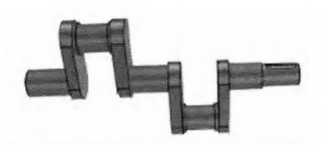
Fig. 3 3D solid model of crankshaft
Figure 3 shows the crankshaft’s 3D solid model. It is built by combining the crankshaft’s geometry with cylindrical components. The 3D sphere feature in CAXA is used for this purpose.
Figure 3 illustrates two connecting rod journals with diameters of 35mm each and three spindle journals with diameters of 35mm, 35mm, and 30mm respectively.
Based on this solid model, a finite element mesh model is generated, as shown in Figure 4. The model optimizes the dynamic structure by minimizing the effects of fillets and oil holes.
In the mesh model, small fillets with a radius less than 5mm and oil passages with diameters less than 12mm are ignored to streamline the structural simulation.
Once the model is complete, enter machining parameters under the “Multi-Axis Machining” tab. Then generate the CNC machining path and produce the G-code.
The generated tool paths are reviewed using CAXA’s compiler assistant to ensure accuracy. Afterward, the lathe setup and assembly of the crankshaft turning fixtures proceed.
Self-centering elements are selected to secure the crankshaft via both bearing journals, and the transitional disk is installed along with the fixture to enable center alignment.
Reposition the 3D sphere onto the transition base. Properly align the central points. This finalizes the crankshaft assembly and prepares it for turning operations.
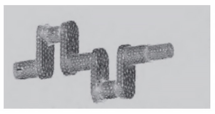
Fig. 4 Crankshaft finite element network model
After establishing the model, simulate the CNC machining.
According to “Machining” and “Multi-axis machining,” fill in the parameters as instructed. The system will calculate and generate the toolpath. Then click on “Machining,” “Post-processing,” “Generate,” and “Generate G code” commands to create the machining code. Finally, use the CAXA compiler assistant to open the folder and check the toolpath.
The second step of crankshaft lathe fixture turning involves selecting self-centering positioning elements. The crankshaft is positioned through both ends of the bearing neck. The parts transition disk and fixture are specifically loaded. Open the fixture’s three-dimensional ball to find the center point, then click on the transition disk circle. Move the fixture above the transition disk. Open the three-dimensional ball again to align the center with the transition base. Click to set the center point. Finally, assemble to complete the transition base and transition disk.
Finally, the clamping and fixture are modeled to produce the crankshaft entity.
Conclusion
In automotive engines, crankshaft quality and performance greatly affect the engine’s overall efficiency and reliability.
Due to the structural complexity and limited rigidity of crankshaft assemblies, high-level quality control is essential throughout the entire machining process.
Modern crankshaft manufacturing involves a wide variety of mechanical processing techniques, each with distinct advantages and suited for specific parts of the crankshaft assembly.
Choosing the appropriate machining technique must be based on detailed analysis of component requirements to ensure optimal compatibility, effectiveness, and precision in production.