In recent years the global industrial competition pattern has undergone major adjustments, and intelligent manufacturing has increasingly become a major trend and core content of future manufacturing development.
Currently, five-axis machine tools are priced higher, have a large footprint, and come with high maintenance costs. They also have a high difficulty in getting started and are prone to operator errors.
In addition, when paired with a robotic arm, the swing space required is large, and the safety is poor. The entire unit also requires a significant amount of space.
This paper focuses on desktop-level five-axis machining centers and six-axis industrial robots. The material loading and unloading is done through the six-axis robot.
The processing of parts is completed in the five-axis machining center.
In this paper, the five-axis machining center of the CNC system, the system is logical, easy to operate, and can be developed according to the needs of the secondary.
The simulation study of this unit as a carrier, the development of five-axis machining process, reasonable planning tool machining trajectory, the use of NX1980 software to prepare the processing program code, through the digital twin platform VE2 and X1 CNC simulation system for simulation verification.
The FIFA World Cup Trophy is the most prestigious award in international soccer (soccer), which is awarded to the winning team of the FIFA World Cup held every four years. In this paper we take the FIFA World Cup as an example for this machining.
Five-axis machining process of the FIFA World Cup
NX software is a flexible and powerful tool. It is an interactive CAD/CAM system produced by Siemens, Germany.
NX software is widely used in mechanical design and mold processing automation. It is applied in various fields such as aerospace, automotive, general machinery, industrial equipment, medical equipment, and other high-tech applications.
In this paper, based on the CAM function in NX1980, the five-axis machining process of the FIFA World Cup is programmed, and after the machining tool path is determined, the NC file is exported through the post-processing file of the machining center.
1. Formulate the five-axis machining process of the FIFA World Cup
The three-dimensional model of the FIFA World Cup is shown in Fig. 1, which has a complex and irregular appearance shape, fine surface relief, and very high requirements for the precision and stability of the machining equipment, and belongs to the typical five-axis machining parts. The blank is made of Φ25×80mm round bar material.
According to the part model, the following five-axis machining process is developed:
① Rough machining: remove the blank residue;
② semi-finishing: complete the processing of the surface relief, to ensure the uniformity of the machining allowance;
③ Finishing: complete the fine processing of the surface relief.
2. Tool trajectory planning for machining Hercules cups
Based on the programming system of NX1980 CNC machining, the Hercules Cup is programmed for CNC machining.
2.1 FIFA World Cup machining toolpath planning
Based on the programming system of NX1980 CNC machining, the FIFA World Cup is programmed for CNC machining.
2.2 Roughing tool trajectory planning
The purpose of roughing is to quickly remove excess blank material, therefore, in order to improve machining efficiency, the selection of cavity milling function respectively on both sides of the blank for fixed-axis machining, which can maximize the machining efficiency.
In NX1980, select a Φ6 flat-bottom milling cutter.
For the toolpath cutting mode, choose the option to follow the part. Set the cut depth to 0.35mm and the machining allowance to 0.25mm.
Set the spindle speed to 1800 r/min and the feed speed to 250 mm/min.
Process the reverse side of the blank. To do this, simply copy the front side of the blank cutter path trajectory.
Set the direction of the cutter axis to the opposite direction. The roughing cutterpath is shown in Figure 2.
2.3 Semi-finishing toolpath planning
Before finishing, in order to remove the material left behind by the larger diameter of the roughing tool, so that the machining allowance of the part during finishing is smaller and more uniform, choose to semi-finish it.
Since the semi-finishing process of the FIFA World Cup needs to complete the surface relief machining, it is necessary to use the five-axis machining function of the five-axis machining center.
In NX1980, select the variable contour milling mode. Choose a Φ3 ball end milling cutter.
Select the projection vector perpendicular to the drive body. Choose the drive method based on the surface area.
Select the modeling of all the contours of the body. Set the cutting mode to helix.
Set the machining allowance to 0.2mm, with a spindle speed of 1,000 r/min and a feed speed of 250 mm/min.
The semi-finishing machining toolpath is shown in Figure 3.
2.4 Finishing tool trajectory planning
The tool trajectory for finishing of FIFA World Cup is consistent with semi-finishing, and the tool used is Φ1 ball end milling cutter, and the machining allowance can be set to 0.
3. Generation of machining program
post-processing that is generated by CAD/CAM software after a series of parameter settings to generate the tool path, the selection of suitable for the current CNC system post-processor to generate CNC NC code.
In NX1980, select the generated roughing, semi-finishing, finishing toolpaths, right-click on the “post-processing”, select the CTB-5Axis-BC.pui post-processing program with machining centers, you can generate the five-axis processing Programs. Part of the machining program for the finishing process is as follows:
N1 (TIME: 0.20)
N2 (ToolName = BALL__MILL)
N3 (D = 2.00R = 1.00F = 4.00L = 75.00)
N4G40G17G90G80G49G21
N5 (VARIABLE_CONTOUR_COPY)
N6G91G28Z0.0
N7G90G54G 00X0.0.0Y0.0.0B0.0C0.0
N8G90G54
N9B0.0.0C0.0
N10S1000M03
N11G43.4H02M08
N12G90G43.4X-.71Y.981Z9.5
N13X-.71Z2.437
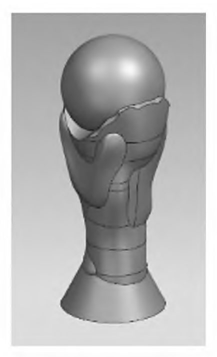
Fig. 1 FIFA World Cup 3D mode
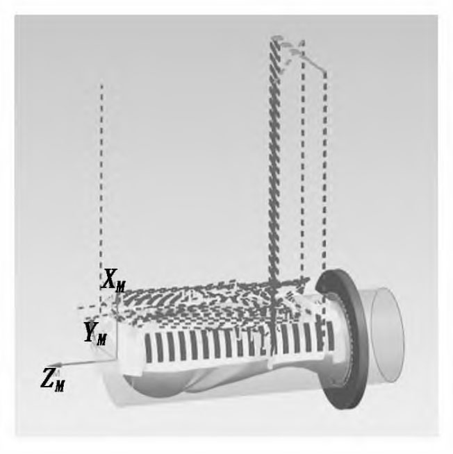
Figure 2 Roughing toolpath
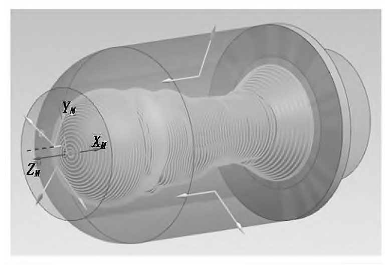
Figure 3 Semi-finishing toolpath
FIFA World Cup VE2 simulation machining setup
VE2 stands for Visual Engineering Education. It has the functions of rapid reconfigurability for intelligent manufacturing systems.
Additionally, VE2 includes CNC machine tool machining simulation, visualization simulation of intelligent manufacturing systems, and robotic demonstrative teaching simulation. It also supports digital twin simulation for intelligent manufacturing systems.
CNC machine tool machining simulation is one of the important functions of VE2.
Under the virtual environment and control platform provided by the software, it connects with the X1 CNC machining simulation system through Python.
The system then simulates the movement of the model. By checking the real use of the three-dimensional model in the scenario, the reasonableness of the machining program can be verified.
This process greatly reduces the risk brought about by unpredictable actual movement situations in the machining process.
This greatly avoids the risk of unpredictable actual motion conditions during machining.
1. Scenario construction of 5-axis machining center
> Model setup
Import the model of 5-axis machining center in Step format into VE2, and select Modeling / Separate Extraction Link / Setting Joint Motion Parameters.
When separating, the X, Y, Z, B, C axes of the model should be separated into independent individuals, and the link of each individual should be extracted and the parent-child relationship should be set according to the motion logic of the actual machine tool.
> Joint Attribute Setting
Set the motion limit of each motion joint according to the travel parameters of the actual machine tool. When setting the movement direction, a right-handed Cartesian coordinate system is used.
Assume the coordinates of the tool relative to the stationary workpiece being machined. Specify the direction of the tool away from the workpiece as the positive direction.
When setting the maximum/minimum movement limits, it is necessary to correspond to the travel of each axis of the real machine tool.
> Linkage module additions
In the Models by Type, find Works Process and add Works TaskControl to the internal, select WorksProcess, set the Task option to MachineProcess, and set SingleCompName to the machine name.
2. 5-Axis Machining Center Behavior Settings
In the Behavior options of the modeling, add the following behaviors:
(1) In the ServoController behavior, add all moving joints in the Joints option, and select the entire machine tool for the root node.
(2) In the RobotExecutor behavior, the Digital Input Signal and Digital Output Signal are set to Input and Output, respectively, and the Controller is set to ServoController.
(3) In the Task behavior, the Connection is set to PythonScript.
3. Programming of loading and unloading of a six-axis industrial robot
Import the six-axis industrial robot model and the blank parts into the VE2 software, then move to the corresponding position and drag the jaws to the end of the robot, as shown in Figure 4.
Figure 4 Position of the six-axis industrial robot and the blank
4. The loading action of the six-axis industrial robot is set as follows:
(1) Select the robot in the program function, click on the “Point-to-Point Motion” function on the left side of the function area, and record the first position.
(2) The gripper moves to the upper end of the blank.
(3) The gripper moves to the clamping place.
(4) Add the yellow button “Set Binary Output Motion”, the output port is 1 and the output value is checked.
(5) The jaws move up to the recorded position.
(6) Move the jaws to the center of the table.
(7) Add “Set binary output action”, output port is 1, output value
is unchecked.
(8) The jaws move up to the recorded position.
(9) The gripper returns to the initial state.
5. The setup sequence of the six-axis industrial robot for the downfeed action is as follows:
(1) Select the robot and record the position in the initial state.
(2) The gripper moves to the top of the part.
(3) The gripper moves to the clamping point.
(4) Add “Set binary output action”, output port is 2, and output value is checked.
(5) Jaws move up to record position.
(6) The jaws move to the table.
(7) Add “Set Binary Output Action”, output port is 2, output value is unchecked.
(8) The jaws are restored to the initial state.
FIFA World Cup X1 CNC machining simulation system settings
X1 software is equipped with a self-developed TSNC CNC system. It is capable of simulating CNC turning, milling, machining centers, and other machine tool operations.
This includes processes such as workpiece installation, tool installation, tool setting, program input, program verification, and machining inspection.
The software creates a highly realistic simulation environment. The simulation of the operating panel is shown in Figure 5.
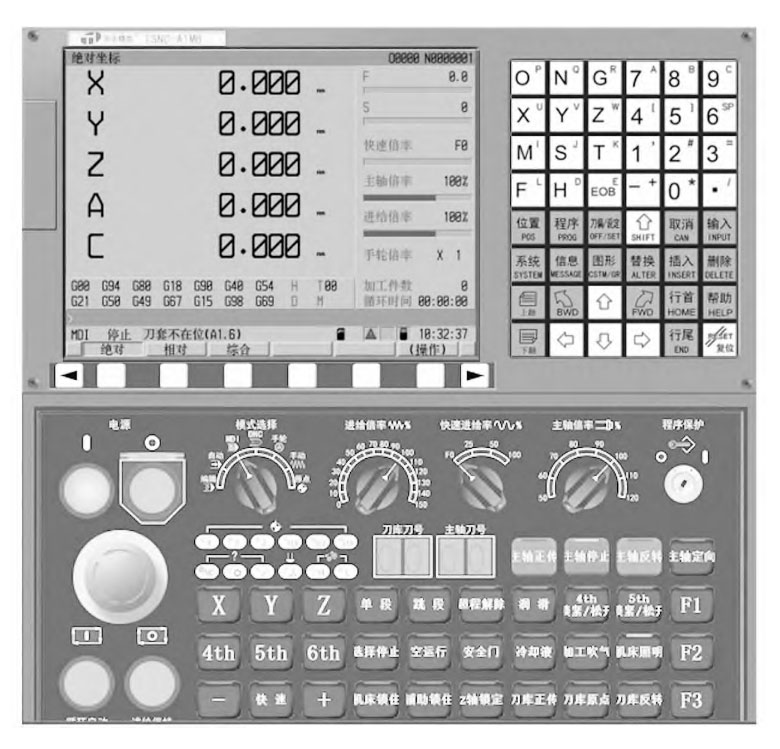
Figure 5 X1 software interface
1. X1 five-axis machining simulation system centering
As the workpiece coordinate system needs to be used in machining, it is necessary to carry out centering and tool setting before machining, so as to determine the origin of the workpiece coordinate system, if the origin of the workpiece coordinate system and the length of the tool is set incorrectly, it will cause tool collision accidents and damage to the equipment.
If the workpiece coordinate system origin and tool length are set incorrectly, it will cause collision and damage to the equipment.
Therefore, setting the workpiece coordinate system origin and tool length correctly is the first step to ensure safe production and simulation machining.
Click on the tool offset / setting / coordinate system, switch to the handwheel mode, the model in VE2 centering, touch a point in X1, select “operation”, click the X / Y axis centering, touch the second point and then click again after the completion of the tool to touch the apex of the blank, the absolute coordinate value of the machine tool is input to the Z-axis, to complete the centering.
2. X1 5-axis machining simulation system import program and running program
Import the post-processing file into the prog___storage folder in the X1 installation directory.
storage folder in the X1 installation directory, switch to edit mode, select machining program, select operation/reading, switch to automatic mode, press and hold the cycle start button.
Select operation/reading, switch to automatic mode, and press and hold the cycle start button to run the program.
The machining simulation effect is shown in Fig. 6.
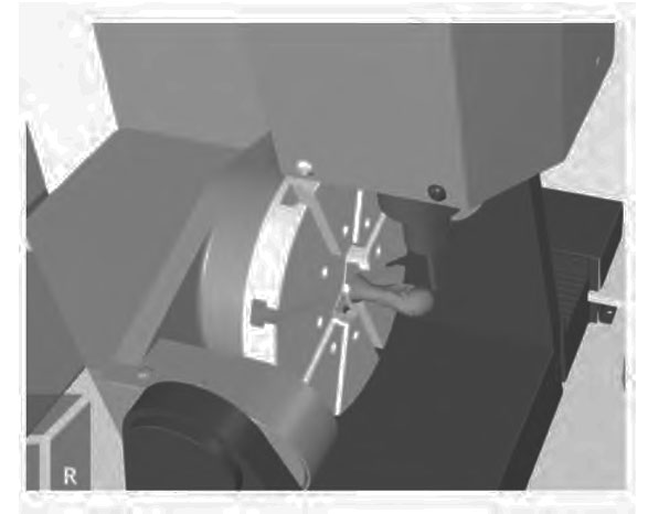
Figure 6 Machining simulation effect of VE2
Conclusion
This paper is based on the digital twin platform VE2 and the X1 CNC machining simulation system. It focuses on five-axis machining of a typical part from the FIFA World Cup.
The machining simulation considers the surface complexity, machining difficulty, and other characteristics of the FIFA World Cup part.
The paper also discusses the development of the five-axis machining process. It includes the reasonable planning of the tool machining trajectory and the use of the NX1980 to generate machining programs.
The goal is to verify the feasibility of the VE2 digital twin platform for simulating five-axis CNC machining and to confirm the correctness of the machining program.
The results show that the simulation of VE2 machining can avoid machine collision, over-travel, tool breakage and other problems due to program errors, while reducing the time of the empty running test cutting program.
Although VE2 can only display the machining trajectory, can not be updated in real time the effect of the cutting of parts, but it can be a simulation of five-axis machining centers in the actual operation of the process.
Overall, the digital twin platform VE2 and X1 CNC machining simulation system can meet the needs of five-axis machining simulation research, providing a theoretical basis and practical foundation for five-axis machining of intelligent manufacturing units.