In machining, cutting, and grinding are the main processes for part molding. The main development direction of cutting is high-speed cutting, including soft, hard, dry, and large feed cutting.
In high-speed cutting, increasing speed reduces cutting force, slows temperature rise, improves surface quality, and lowers costs. To achieve this, suitable tool materials, structure, and monitoring technology are needed.
High-speed cutting tool materials development status
From the mid-nineteenth century to the present, the development of tool materials is shown in Table 1.
Table 1 The development process of tool materials
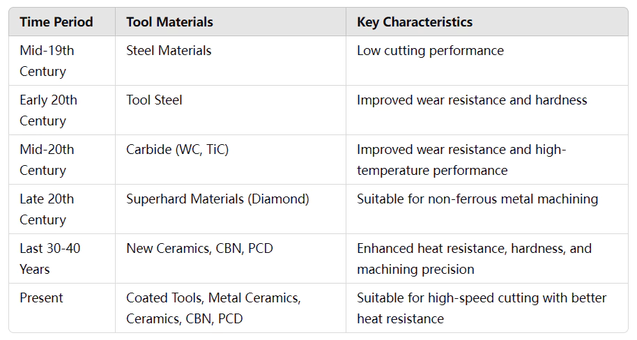
The progress of tool materials has promoted the development of cutting and processing technology. The impact of tool materials is particularly critical when cutting at high speeds.
As cutting speed increases, tool steel tends to burn or wear due to its low heat resistance. Cemented carbide, composed mainly of WC or TiC, has a metal bond that limits its high-temperature resistance.
Diamond oxidizes at about 700°C, but performs well when used for machining non-ferrous metals.
In the last 30 or 40 years, breakthroughs in cutting tool materials have solved the problems in high-speed cutting. New tool materials (such as ceramics, CBN, etc.) have excellent heat resistance.
Whisker-toughened ceramics and coating technology have increased tool hardness and improved the balance between hardness and toughness. Polycrystalline Cubic Boron Nitride (PCBN) has a hardness of 35004500HV and is the tool of choice for high-speed cutting of hardened steel.
Polycrystalline diamond (PCD) has a hardness of 6000-10000 HV. It is suitable for high-speed cutting of non-ferrous metals and some ferrous metals.
At present, suitable for high-speed cutting tools including coated tools, metal ceramic tools, ceramic tools, CBN, and PCD tools.
1. International high-speed cutting tool materials development status quo
(1) coated tool materials
Coated tools enhance surface hardness and cutting performance by coating a thin film of metal compounds on the tool substrate. Commonly used tool matrix materials include high-speed steel, cemented carbide, metal cameras, mics, and ceramics.
The coating can be single, double, multi-layer, or a composite of several materials.
Common coating materials for hard-coated tools include TiN, TiCN, TiAIN, and TiAlCN.
Among them, TiAIN has excellent performance in high-speed cutting, and the maximum working temperature can reach 800℃.
Recent PVD coatings like CBN, CNX, Al₂O₃, and TiN/NbN, TiN/VN have good thermal stability at high temperatures. These coatings are ideal for high-speed cutting. Diamond film-coated tools are suitable for machining non-ferrous metals.
Soft-coated tools (e.g., MoS₂, WS₂ coated HSS) are used for machining high-strength aluminum alloys, titanium alloys, and precious metals.
In addition, the latest nano-coated tool materials have broad application prospects in high-speed cutting. The nano TiN/AIN composite coated milling cutter blades by Sumitomo Corporation have 2000 layers. Each layer is 2.5nm thick.
(2) Metal-ceramic cutting tool materials
Metal ceramics have high room-temperature hardness, high-temperature hardness, and good wear resistance.
The main types include:
① high wear resistance TiC-based cemented carbide (TiC + Ni or Mo).
② High toughness TiC-based Cemented Carbide (TiC+Tac+WC).
③Tough TiN-based Cemented Carbide (TiN as the main body).
④ High toughness TiCN-based Cemented Carbide (TiCN+NbC).
Metal-ceramic tools are suitable for cutting speeds of 300 to 500 m/min. They are ideal for high-speed finish turning of steel and cast iron.
(3) Ceramic tool materials
Ceramic tool materials are mainly divided into two categories: alumina-based and silicon nitride-based. They are made by adding carbides, nitrides, boboridesss, and oxides in the alumina and silicon nitride matrix. In addition, there are multiphase ceramic materials.
Currently, about 20 alumina-based ceramic tools have been developed internationally, making up 2/3 of all ceramic tools. About 10 kinds of silicon nitride-based ceramic tools account for 1/3 of the total number of ceramic tools.
Ceramic tools can cut soft steel (A3 steel), hardened steel, cast iron, alloys, and other materials at speeds of 200-1000 m/min.
(4) CBN cutting tool materials
Cubic nitride nitrogen (CBN) cutting tools have extremely high hardness and red hardness. It is an ideal material for high-speed finishing or semi-finishing machining of hardened steel, cold-hardened cast iron, and high-temperature alloys.
CBN tools can obtain good surface roughness when machining high-hardness parts. Therefore, the use of CBN tools to cut hardened steel can be realized “to cut instead of grinding”.
Due to the high price and weight of CBN cutter blanks, CBN cutter blanks are usually welded to the corner of the indexable carbide inserts, and only one tip is processed. Studies have shown that pure CBN tools do not give optimal results in some cases.
For this reason, a variety of CBN inserts and CBN-ceramic composite inserts have been developed internationally. The CBN content of these inserts varies according to different machining requirements.
(5) PCD cutter materials
Polycrystalline diamond (PCD) material has high hardness, wear resistance, thermal conductivity, and low friction. PCD tools are ideal for high-speed, high-precision machining of non-ferrous metals and wear-resistant non-metallic materials.
Multi-tooth welded PCD tools have a smallcutting-edgee runout and are suitable for mass machining of non-ferrous metal parts. They are especially useful for machining shaped surfaces, holes, and stepped holes.
For example, a φ100mm six-tooth high-speed milling cutter with an aluminum matrix cutter plate can reach a maximum cutting speed of 7000m/min.
The size of PCD particles significantly impacts tool performance. PCD tools with a 10-25μm particle size are best for cutting aluminum alloys and cemented carbide with ≥12% Si content, at cutting speeds of 300-1500m/min.
PCD tools with an 89μm particle size are suited for cutting aluminum alloys and general non-metallic materials with ≤12% Si content, at cutting speeds of 500-3500m/min.
PCD tools with a particle size of 4~5μm are suitable for cutting materials such as FRP, wood, or pure aluminum.
(6) high-speed steel, carbide cutting tool materials.
High-performance cobalt high-speed steel, powder metallurgy high-speed site, el and integral cemented carbide materials, have become the mainstream materials for manufacturing gear-cutting tools. These materials can be used for high-speed cutting of gears.
The new powder metallurgy material is made of cemented carbide powder and high-speed steel powder. The hob is made of it, and the rolling speed can reach 150~180m/min. If TiAIN coating treatment, it can be applied to high-speed dry cutting.
Fine-grained carbide twist drill, coated with a heat-resistant, wear-resistant coating, can be used in high-speed wet machining of structural steel and alloy steel, up to 200m/min cutting speed, 1600mm/min feed speed.
In high-speed dry drilling, the cutting speed can reach 150m/min and the feed speed can reach 1200mm/min.
Fine-grained carbide high-speed tap processing ordinary cast iron, the highest tapping speed up to 100m/min.
2. China’s high-speed cutting tool material development status quo
China’s commonly used cutting tool materials for high-speed steel and carbide, mainly ordinary high-speed steel and carbide. Cemented carbide welding tools are widely used and aluminum high-speed steel and powder metallurgy steel are used less.
The quality of domestic high-speed steel has declined, and the quality of cobalt-containing steel is poor. High-performance cemented carbide and ultra-fine particle alloys are used less, and special grades are scarce. The gap between tool coating technology and the international level is large, and diamond film and TiCN coating are still under development.
High-speed cutting tool materials need to be developed. China’s ceramic tool research is more adequate, and nd has established a cutting reliability design system. Domestic alumina-based ceramic tools have nearly 20 kinds, and about 10 kinds of silicon nitride-based ceramics, production capacity is large.
Ceramic tool performance is not inferior to the internationally developed ceramic and carbide composite inserts and other new products. The gap is mainly in the manufacturing process and the quality of certain special ceramics. Ceramic cutting tools to promote the application of less than-developed countries.
China has developed a variety of CBN and PCD cutting tools, CBN is mainly used for hard steel and hard-to-machine materials, PCD for aluminum alloys. However the specifications are not complete, some of the quality is poor, and the application of limited promotion.
High-speed cutting tool technology status
1. Dynamic balance technology of high-speed cutting tool system
(1)Imbalance Issues in High-Speed Cutting Tool Systems
The imbalance of the tool system (cutting edge, tool shank, tool disk, clamping device) can lead to a variety of problems.
First, it will shorten tool life and increase downtime.
Second, it increases machining surface roughness and reduces machining dimensional accuracy.
Finally, it reduces spindle-bearing life.
For high-speed cutting tool systems, the balancing issue is even more critical.
Generally, the balance correction for small tools is only a few grams.
Compact tools can be treated with static balancing.
For tools with large overhang lengths, dynamic balancing is required.
(2)Factors Contributing to Tool System Imbalance
The main factors of high-speed cutting tool system imbalance include:
① The balance limit and residual unbalance of the tool.
② Tool structure imbalance.
③ Tool shank asymmetry.
④ tool and collet installation asymmetry (such as single-edged boring tool).
If the tool has an equivalent unbalanced mass m(g) at a distance e(mm) from the center of rotation, the tool’s unbalanced amount U(g-mm) can be defined as the product of the unbalanced mass and eccentricity, i.e., U = m × e.
In addition, G is a parameter that reflects the relationship between the tool balance amount and the rotational speed n(r/min).
(3)Balancing Methods and Standards

where ω: angular velocity
The resulting inertial centrifugal force Fe(N) is

Fig. 1 shows the relationship between centrifugal force, spindle speed, and tool imbalance.
Centrifugal force applies changing radial forces to the spindle bearing, causing accelerated wear, machine vibration, and potential accidents. As seen in the graph, centrifugal force increases by a square multiple with spindle speed.
Thus, high-speed cutting tools, especially rotary tools, must be dynamically balanced in addition to static balancing. Dynamic balancing should match the tool’s speed range to ensure optimal results.
When balancing, first balance the tool, collet, and spindle individually. Then, balance the tool-collet combination, and finally, balance the tool and spindle together.
A fine adjustment screw or a boring tool with a rotating compensation ring and internal counterweight can fine-tune the balance.
Currently, no uniform tool balancing standard exists outside China, and opinions differ on the G value in ISO 1940-1.
Some companies use G1 as the standard (10000r/min, 1μm eccentricity), while others use G2.5 for tools over 6000r/min.
Balancing requirements for high-speed cutting rotary tools and tool perch systems can follow the G1 or G2.5 standard in Fig. 2.
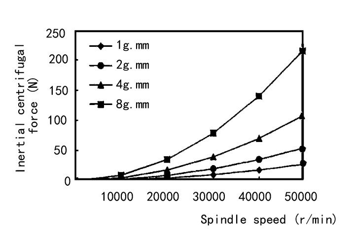
Fig. 1 Relationship between the centrifugal force of inertia and spindle speed and toolunbalancedde amount
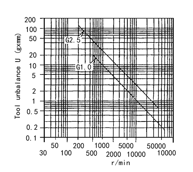
Fig. 2 High-speed cutting rotary tools a tool holder system balance requirements
2. High-speed cutting rotary tool shank system
During high-speed cutting, the tool needs to maintain sufficient clamping force to prevent damage to the tool by centrifugal force. Therefore, the tool clamping device has strict requirements.
The 7:24 solid taper shank tool system used for many years has some disadvantages:
①The taper connection leads to low rigidity of the tool holder and spindle, especially when the spindle speed exceeds 10,000 r/min, the rigidity problem is more serious.
② When automatic tool change (ATC), the tool repeat positioning accuracy is low, making it difficult to realize high-precision machining.
③ When rotating at high speed, the front end of the spindle is expanded by centrifugal force, which is easy to causes the spindle and the thtapereder surface of the tool holder to disengage, generating a large radial runout (up to 15μm), reducing the contact rigidity of the tool holholdernd may even cause safety accidents.
Solution: Dual-Positioning Tool Holders
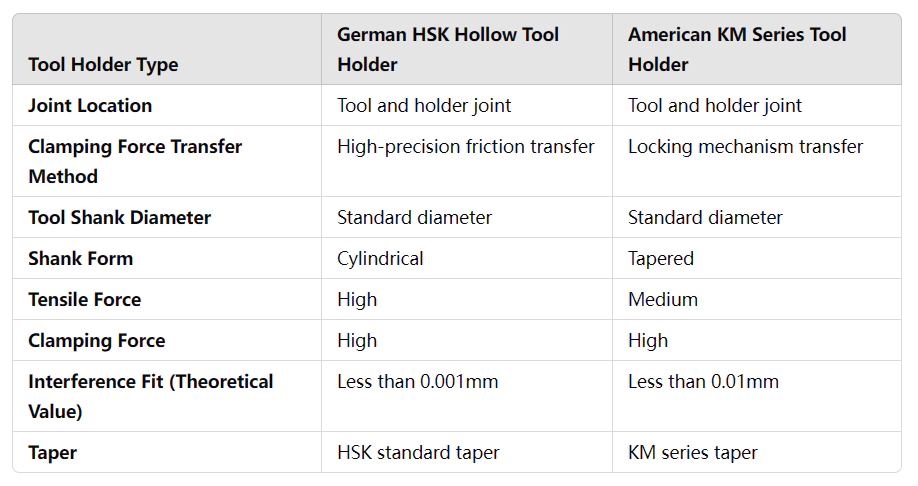
Therefore, the traditional long taper tool holder is not suitable for high-speed cutting machining. To solve these problems, the development of a dual-positioning type tool holder (such as the German HSK hollow tool holder and the United States KM series tool holder).
This kind of tool holder has high accuracy when installed by taper part and spindle end face positioning at the same time. The shank can be firmly locked under high-speed rotation, radial runout does not exceed 5μm, ensuring high static and dynamic rigidity. Therefore, these tool holders are particularly suitable for high-speed cutting.
Table 2 lists the structural characteristics of HSK and KM tool holders
HSK integral shanks are of balanced design, with shanks of type A, B, C, D, E, and F (see Fig. 3). In practice, the HSK50 and HSK63 shanks are suitable for spindle speeds of up to 25,000 r/min, and the HSK100 shanks are suitable for spindle speeds of up to 12,000 r/min.
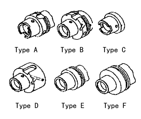
Fig. 3 HSK shank types
3. High-speed cutting tool safety
Cutting tool safety mainly involves high-speed milling cutters and borintoolsol, especially high-speed millicuttersters. High-speed milling is a key process, but ordinary milling cutter can not meet the requirements, so high-speed milling cutter safety research is particularly important.
Germany since the early 1990s began to study the safety of high-speed milling cutter technology, the development of the DIN6589-1 standard, and the provisions of the failure test methods and guidelines, to become a guiding document for safety research.
Failure Modes and Design Considerations
The safety of indexable milling cutters for high-speed cutting depends on both the cutter body strength and the reliability of the insert clamping. Centrifugal force is the main cause of cutter breakage, so the body must resist this force.
During design, FEM modeling analyzes the cutter’s strength and deformation. This calculates stresses at different speeds, simulates failure, and improves the design. Experimental data establishes the FEM model’s boundary conditions, enhancing design accuracy.
Calculations and experiments show two failure modes in ultra-high-speed cutting. First, the screw shears off, and the insert or clamping element is thrown. Second, the cutter body bursts. Failure usually begins with parts flying at low speed, then progresses as cutter body strength is exceeded.
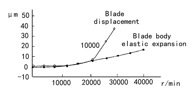
Fig. 4 shows the relationship between failure and rotational speed. At rest, the clamping force causes centripetal deformation. As speed increases, the cutter body and blade expand. The centrifugal force overcomes the screw clamping force, and the blade eventually disengages and is thrown.
4.Structuree of high-speed indexable face milling cutter
According to safety requirements, inserts cannot be clamped by friction when cutting at high speed (n > 6000 r/min). Inserts with a center hole must be clamped by screws.
Critical safety parameters include the eccentricity of the center hole, its shape, and the screw. These affect the preload when the screw is clamped. Excessive preload may cause screw deformation and reduce the clamping system’s failure speed.
The tool can also be clamped in an empty tool slot with a chuck for accurate positioning. The clamping force on the insert and tool holder should align with the centrifugal force.
When clamping the insert, apply the specified torque and use qualified screws. Before tightening the screws, lubricant should be applied to minimize torque loss. Also, screws need to be inspected and replaced periodically.
Design Considerations for Milling Cutter Safety
For safety, the knife body design should minimize mass, reduce diameter, and increase height. Lightweight, high-strength materials should be used. High-speed milling cutters already use high-strength aluminum alloys for the cutter body.
Slots on the cutter body (e.g., insert slots, chip holders, keyways) can cause stress concentration, reducing strength. Avoid through-cut slots and reduce sharp corners to prevent this.
The number of machine-clamped parts should be minimized. The cutter body should be symmetrical to the rotary axis, ensuring the center of gravity aligns with the axis. For unequal tooth cutters, adjust mass distribution for even expansion. The clamping adjustment mechanism should eliminate play and ensure repeatable positioning.
5. High-speed cutting tool monitoring technology
Tool monitoring technology is vital to the safety of high-speed cutting machining. It mainly controls wear by monitoring the cutting force. Another method is to monitor the machine’s power to indirectly obtain wear information. It can also be monitored by detecting breakage or failure.
Currently, the research and application of high-speed cutting monitoring technology are still insufficient outside China.
Conclusion
High-speed cutting technology is an advanced manufacturing technology with a broad application prospect. Cutting tools and related technologies are the key trealizingze high-speed cutting. The research and development of tool materials, tool structure, and monitoring technology should be strengthened.
The safety technology standard of high-speed cutting tools is established. This will improve the cutting efficiency and quality of China’s machinery manufacturing industry.
