Aerospace industry products are commonly used in thin-walled parts, complex structures, and high-precision requirements. Due to poor stiffness, processing deformation caused by cutting force is easy to produce, resulting in wall thickness on the thick, thin size over the phenomenon.
The standard method used in the factory is to cut several times without feed after the last tool travels in finishing and is combined with manual grinding. Although this method can remove most of the residual material, the adult increased machining hours, and machining surface roughness will be significantly reduced [1].
For thin-walled parts processing wall thickness accuracy control problems, Russia uses a particular angle of conical tool processing but can not completely solve the problem; the limitations’ application is also extensive. The current development of high-speed cutting technology can solve the problem of thin-walled parts processing but requires high-speed cutting machine tools or machining centers.
This paper proposes the application of the finite element method to analyze the thin-walled parts due to the deformation caused by the cutting force and calculated machining error, based on which a CNC compensation method: through the overcutting compensation to let the knife error, finishing a tool to achieve the machining accuracy requirements.
1. thin-walled parts machining error
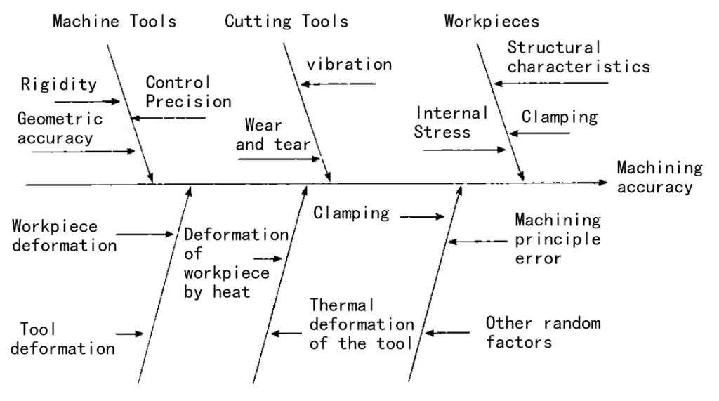
Figure 1 Factors affecting the machining accuracy of parts
CNC machining of thin-walled parts, the workpiece due to lack of rigidity caused by machining deformation has become the principal contradiction affecting dimensional accuracy [2]. Thin-walled frame parts machining simplified schematic diagram in Figure 2.
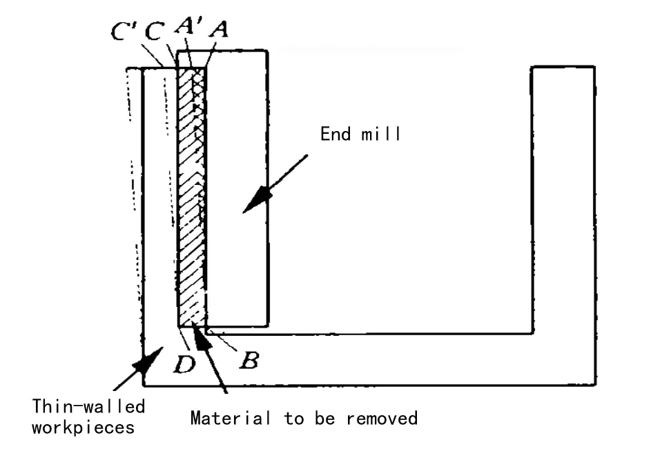
Figure 2 Thin-walled parts machining schematic
Using an end milling cutter, milling thin-walled surface AB should be removed from the shaded part ABDC, but due to the role of cutting force, so that the thin-walled parts of the elastic deformation, A, C two points were moved to the A’, C’ two points, assuming that the tool stiffness is much greater than the stiffness of the thin-walled part of the tool only to remove the part of the A’BDC material.
After the thin-walled elastic recovery, the residual CDC part of the material is not removed, resulting in a wall thickness processing error. The wall thickness processing overshoot in thin-walled parts is mainly due to the knife cutting a piece of material.
Thus, a new idea of deformation control of thin-walled parts is proposed: the deformation of thin-walled parts is calculated by finite element analysis, and then the residual part of the material is removed using CNC machining compensation.
After the side wall’s elastic recovery, the workpiece’s wall thickness just reaches the tolerance requirement. Therefore, the key to the problem is to solve certain processing conditions of thin-walled parts using deformation analysis and calculation methods.
2. thin-walled parts machining deformation analysis
2.1 Establishment of force model
To solve the problem of controlling the accuracy of machining of thin-walled parts, the force model, deformation model, and CNC compensation model need to be established. The keyword is the establishment of an accurate force model. Based on analysis and verification, this paper establishes a spiral end mill force model in the existing literature.
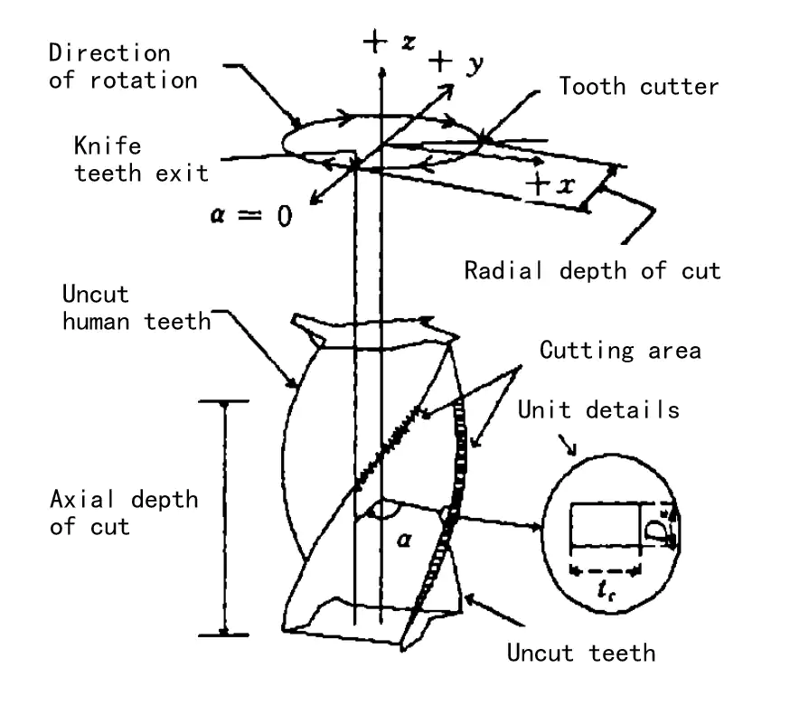
Figure 3 for the end milling milling force analysis map
The size of the cutting force is related to the cutting thickness [3,4], to facilitate the analysis, the total cutting area is divided into the illustrated loading unit through the calculation of all in the cutting area of each Figure 3 vertical milling force analysis chart unit load, you can get the spatial distribution of force state.
The unit cutting force can be decomposed into tangential and radial cutting forces [5] and has the following relationship.

DFT is the unit tangential cutting force, DFR is the unit radial cutting force, DZ is the axial width of the load unit, and tc is the unit thickness: KT and KR are constants derived from experiments. It can be approximated as a function of tK for the average unit thickness tc; for a particular cutting parameter, KT, KR is constant.
According to the experimental data, it is assumed that the relationship between KT, KR, and the feed per tooth fz, axial depth of cut αρ, and radial depth of cut αe can be described by a polynomial model.

This paper solves the polynomial model coefficients by average cutting force tests. The test is carried out on a Mikron ucp710 machining center; the tool is a cemented carbide monoblock end mill, and the material is aluminum alloy LY12CZ. All coefficients can be solved by regression analysis.
2.2 Typical thin-walled structure
To illustrate the problem, this paper selects the thin-walled box as the typical structure of thin-walled parts (see Figure 4). Workpiece material 7075-T6, Young’s modulus fz– 77 GPa, density P- 2.78×10°kg/m, Poisson’s ratio γ= 0.33
2.3 Some basic assumptions
(1) To simplify the model and calculation, assuming that the milling thickness is significantly smaller than the wall thickness of the processed material, the modeling can be ignored when the wall thickness difference between the surface of the processed surface and the surface to be processed, according to the calculation of equal wall thickness.
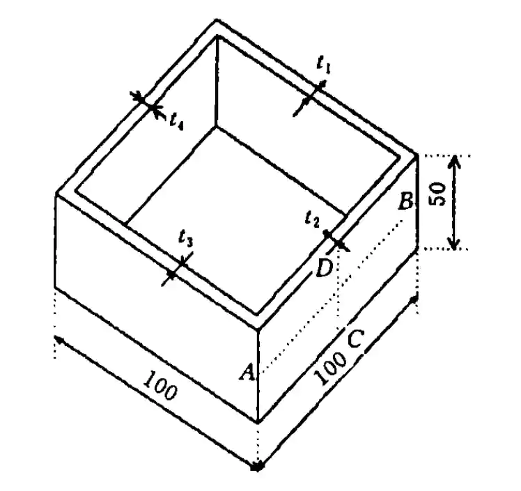
Figure 4 Typical structure and size
(2) Assuming that the entire process is in the elastic range of the material
(3) Assume that the material is completely isotropic.
2.4 Working conditions and analysis
As shown in Fig. 5, a distributed load along the helix direction is applied to the frame wall at a particular instant when machining the frame wall with a spiral end mill. Because the tool speed is much larger than the feed speed, it can be assumed that the tool axis is fixed in a particular feed position. The cutter teeth move from the bottom up along the A direction until the workpiece is cut out, forming the machined surface at the axis [6,7].
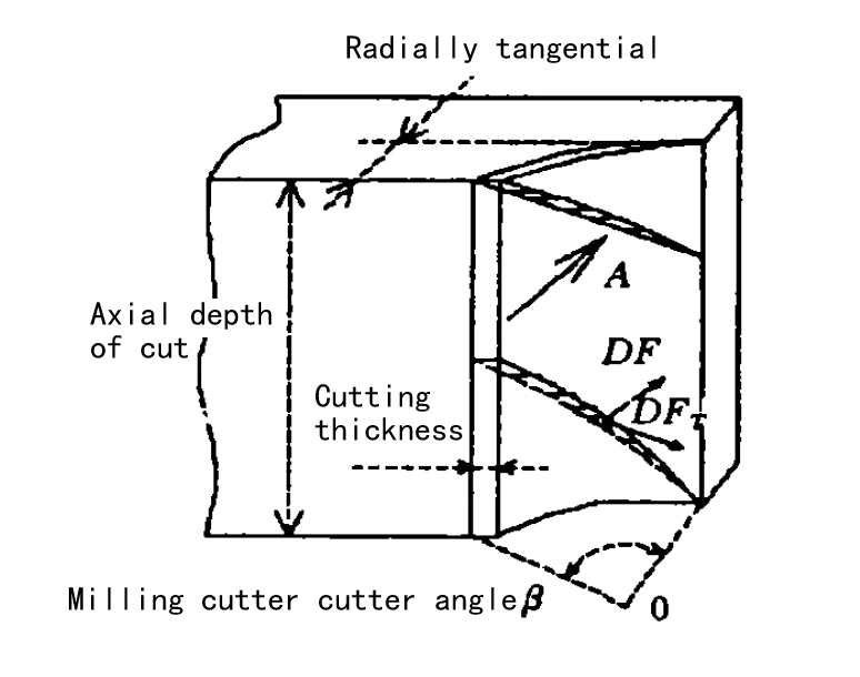
Fig. 5 Spatial distribution of instantaneous radial force
In actual machining, because the radial depth of cut is small, the distribution of loads in the cut-in region of Fig. 5 can be approximated to the mesh nodes, and the deformation of each part can be easily and quickly calculated using finite element analysis software. For illustration, the following scheme is taken as an example.
Scenario 1 analyzes the deformation of different wall thicknesses in the x-direction under the same loading conditions. The specific conditions are a radial depth of cut of 0.4 mm, an axial depth of cut of 24 mm, a rotational speed of 6000 r/m, feed of 0.04 mm per tooth, and wall thicknesses of 1.5 mm, 2 mm, and 3.0 mm, respectively.
Scenario 2 analyzes the frame’s deformation at different positions (x=25, x=50) under the same loading conditions and wall thickness. The loading conditions are the same as in Scheme I. The wall thickness is chosen to be 3 mm.
3. Computational analysis
(1) Analyzing Thin-Walled Parts with ANSYS 5.7
ANSYS 5.7 simulates thin-walled part deformation during milling. Vacuum suction cups clamp the part, and end mills machine it on all sides. The model of the frame is based on typical thin-walled structures. The simulation uses the Elastic 8node93 unit. It applies machining conditions to the force model and calculates forces at each node.
(2) Pre-Analysis Results
Pre-analysis shows minimal effect from horizontal forces on deformation in the thickness direction. The workpiece mesh is shown in Figure 6.
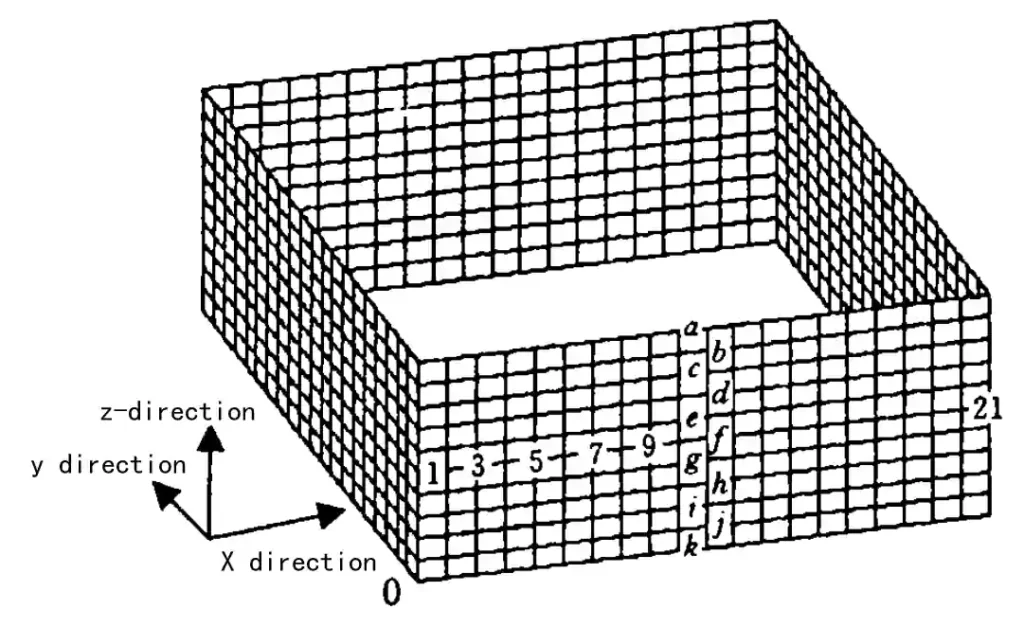
Figure 6: Workpiece Mesh Map
(3) Instantaneous Deformation of the Workpiece
In Program 1, when the milling cutter is at x = 50, Figure 7 shows the deformation curve in the z-direction at half the workpiece’s height.
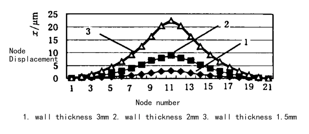
Figure 7: Displacement of the Frame at Each Node in the X-direction
Deformation is greatest at the midpoint of the thin wall in the z-direction. The constrained ends show no deformation.
(4) Deformation Along the Z-Direction
Figure 8 shows the deformation in the frame’s middle section at x = 50 (3 wall thicknesses). Deformation is inversely proportional to wall thickness. Thinner walls deform more. The top part deforms, while the bottom, fixed by the suction cup, shows little deformation. The cutting area at the top has minimal deformation due to the tool’s helix angle.
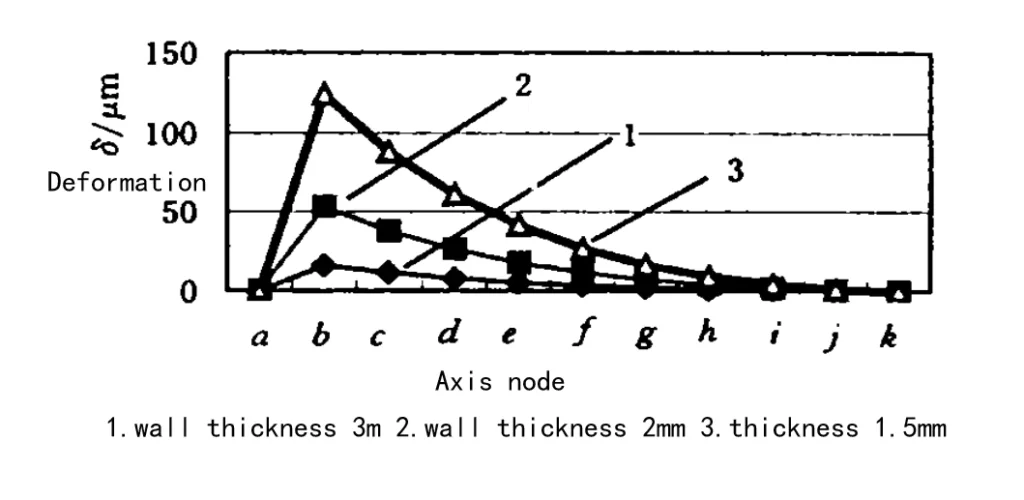
Figure 8: Deformation of Each Node Along the Z-Direction at x = 50 (Scheme 1)
(5) Deformation in Scheme II
Figure 9 shows the deformation in the z-direction for Scheme II. Deformation is greatest at the midpoint (x = 50) compared to x = 25.
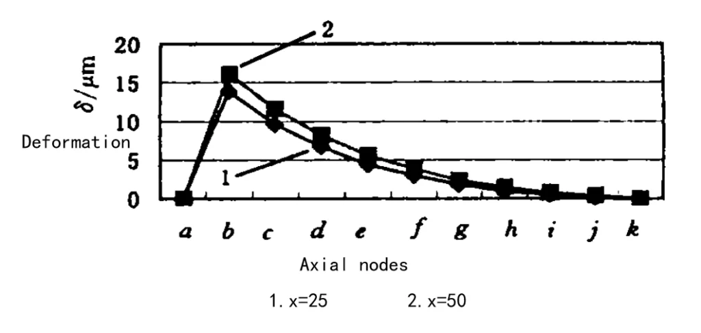
Fig. 9 Deformation of each node along the z direction (Scheme II)
4. Numerical control compensation scheme
According to the finite element calculation results of the above analysis program, it can be found that, in the milling of a thin-walled frame, due to the action of the cutting force, the frame wall will be elastic deformation, the amount of deformation along the height of the direction of the parabola gradually increases, the amount of deformation in a specific limit can be approximated as a straight line: the deformation along the length of the frame wall at the midpoint of the length direction is greater than the other positions (x-25).
The deformation along the length of the frame wall is more significant at the midpoint but almost zero at the two endpoints.
Under certain machining conditions, the thinner the wall thickness, the more serious the deformation, the greater the error generated. Due to the deformation of the knife phenomenon, resulting in a part of the material being left behind, the formation of the thin thickness of the upper and lower thickness of the thin over difference is fully consistent with the actual processing results.
Finite element analysis can guide the selection of reasonable machining dosage in the finishing process if the tool in the original CNC programming according to the degree of deformation in the trajectory of the tool with an additional deflection to compensate for the deformation of the amount of letting the tool, can be eliminated letting the tool error. Thin-walled parts CNC compensation processing and control of machining accuracy of the process are shown in Figure 10.
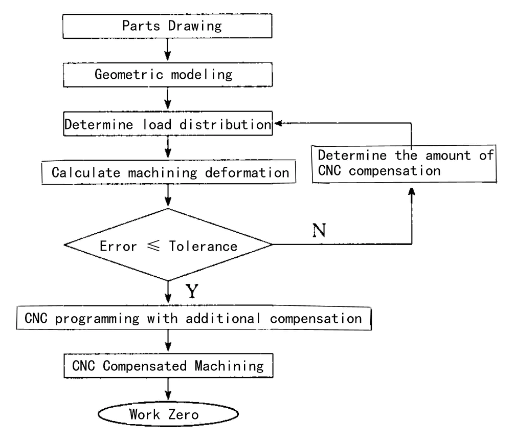
Figure 10 Thin-walled parts CNC compensation machining flow chart
5. Conclusion and outlook
(1) Machining Deformation and Surface Thickness
Machining deformation and surface thickness are inversely proportional to the thickness of the other three surfaces. The influence of thinness is minimal.
(2) Deformation Along the Height Direction
Deformation along the height direction of the frame wall changes parabolically. When deformation is limited, the maximum deformation near the wall opening forms a straight line.
(3) Deformation Along the Frame Length
Deformation along the frame wall’s length is greatest at the midpoint. The deformation is nearly zero at the endpoints. The frame wall’s 3D deformation is saddle-shaped.
(4) Effect of Load Distribution on Deformation
Different load distributions affect deformation distribution. In automation and virtual manufacturing, the finite element method estimates processing errors.
6. Conclusion and Further Considerations
These conclusions guide wall thickness accuracy control for thin-walled parts. However, accurate deformation analysis requires precise load modeling, based on cutting force experiments.
Iterative analysis of machining deformation and CNC offset compensation can remove most residual material.
For further accuracy, consider tool deformation, workpiece clamping, cutting temperature, and tool wear. CNC compensation in finishing ensures wall thickness accuracy for high-efficiency, economical, and quality processing of thin-walled parts.
References
- [1]Altintas Y. Dynamic Peripheral Milling of Flexible Structures. Trans ASME J Eng Ind, 1992, 114(2):137~145
- [2]Tsai Jer Shyong,ChungLi Liao .Finite-element Modeling of Statie Surface Errors in the Peripheral Milling of Thin-walled Workpieces.J. of Mater. Pmc. Tech. ,1999,94.235~246
- [3] Zhang Youzhen. Theory of Metal Cutting. Beijing: Aviation Industry Press 1987.67~76
- [4] L Zheng, YUN Shun, Steven Y Liang.Three-dimensional cutting Force Analysis in End Milling: International Journal of Mechanical Sciences, 1996, 38(3)259~269
- [5]Kine W A, Devor R E. Lindberg R. The Prediction of Cutting Forces in End Milling with Application to Cornering Cuts. International Journal of Machine Tool Design and Research,1982,22(1)7~22
- [6]Budak E, Altintas Y. Modeling and Avoidance of Staticfom Errors in Peripheral Milling of Plates. Int. J. Mach.Tools Manuf.1995, 35(3):459~476Sutherand J W, Devor R E. An Improved Method for Cutting Force and Surface Error Prediction in Flexible EndMilling Systems. Trans. ASME, 」. Eng: Ind, 1986, 108.269~279
- [7]Sutherland J W, Devor R E. An Improved Method for Cutting Force and Surface Error Prediction in Flexible EndMilling Systems. Trans. ASME, 」. Eng. Ind, 1986, 108269~279
