Deep hole drilling technology is a complicated precision machining technology used in the familiar military field and widely used in aerospace, mold manufacturing, the automotive industry, etc. It mainly solves the manufacturing need for processing holes with large depth-to-diameter ratios (depth 10 times or more than the diameter), prone to hole offset and poor surface roughness in conventional drilling.
Various new deep-hole machining technologies have emerged during technological development, namely gun drilling, BTA drilling, jet drilling, and DF drilling systems.
Engineers primarily use the gun drilling system to process small-diameter (2–30mm) holes, making it the most common deep-hole drilling and machining method for small—and medium-sized mass production.
Operators primarily use the BTA drilling system for deep-hole drilling and machining with diameters greater than 12mm, making it the top choice for continuous deep-hole machining involving large quantities and high loads.
Jet drilling system is a highly efficient method of deep hole machining, but the diameter of the holes processed cannot be less than 18mm.
The DF drilling system has the advantages of both BTA drilling and suction drilling systems. It increases the drilling diameter range (minimum diameter up to 6mm) and improves machining accuracy and efficiency.
The following example involves a stepped deep hole machining problem encountered during actual work. After gathering relevant information, several common machining methods were screened. Through comparative analysis, the most suitable method was selected. A special tool was then designed and applied to real product manufacturing. This achieved high-precision, small-batch, and stable deep hole machining, offering ideas and solutions for the industry.
Processing situation analysis
Figure 1 shows the structure of the deep hole. The diameter of the beginning of the deep hole is 15.97 (0/-0.1) mm, 258 mm deep. The diameter of the end of the deep hole is 6 mm, 15 mm deep. The two holes pass through the 120 ° chamfer transition.
The pipe wall welded onto the small receiver contains a deep hole. The arc-shaped pipe and its size make medium and large milling and boring machines the most suitable choice for processing. Pipe and small receiver material are 304 stainless steel.
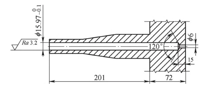
Figure 1 deep hole structure
Problems and analysis
1.Stainless steel material is difficult to cut
When stainless steel is cut, it tends to deform plastically. The resulting chips are difficult to break or separate. As a result, cutting stainless steel often causes a sticky knife phenomenon. The cutting force increases significantly, which raises the cutting temperature. This leads to faster tool wear and negatively affects the surface quality of the workpiece.
To improve stainless steel machining quality, practical measures should be taken based on its cutting characteristics. This includes optimizing tool materials, adjusting cutting parameters, and selecting effective cooling methods.
2.Hole diameter is small, large aspect ratio machining problems
Deep hole machining has always been a problem. Combined with the working conditions involved in this paper, Table 1 analyzes the advantages and disadvantages of these four types of deep-hole machining.
Based on the processing method and workpiece conditions, milling and boring or special deep-hole drilling are selected for testing. The hole must meet dimensional accuracy within ±0.1 mm and surface roughness of Ra ≤ 3.2 μm.
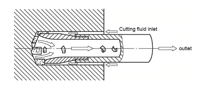
Figure 2 BTA principle schematic
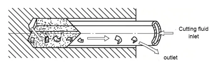
Fig 3 Schematic diagram of gun drill principle
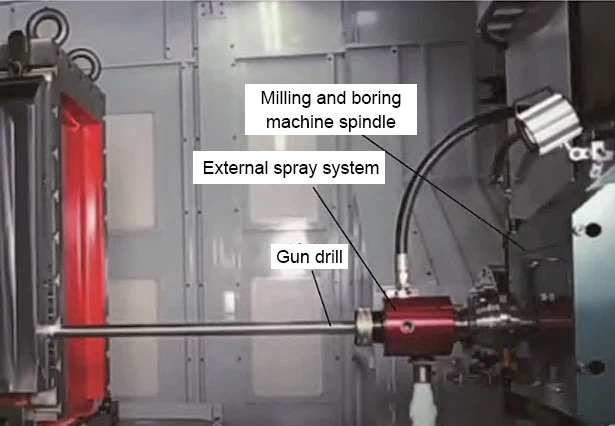
Figure 4 Structure of deep hole drill for milling and boring
The team tested deep-hole drilling for milling and boring using two kinds of tools. They adjusted the cutting parameters during machining. However, the test piece holes failed to meet the required Ra ≤ 3.2 μm surface roughness and showed local overtolerance.
Deep hole drilling for milling and boring carries a greater risk of surface roughness failure and local size overshooting in the actual processing.
In the test piece of special tool machining drilling, without considering the processing time, we can effectively control the hole size tolerance and ensure surface roughness.
Traditional drilling→expanding→reaming can better control the hole size, and manual reaming also reduces the surface roughness value of the inner wall of the hole.
3.Difficulty in processing shaped holes
Due to the workpiece’s variable diameter size, few existing forming tools can process shaped holes, so a special tool is necessary to process 120° chamfers and φ 6mm holes.
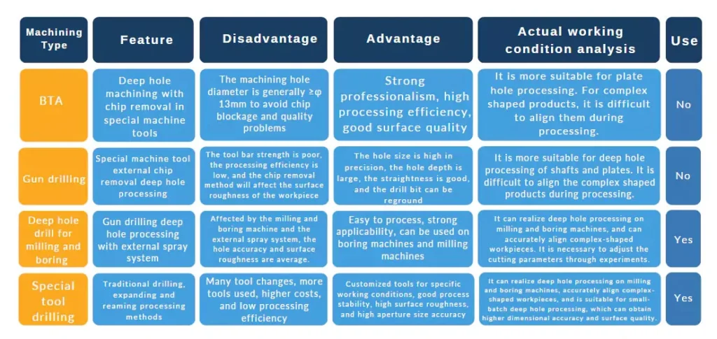
Table 1 Advantages and disadvantages of 4 kinds of deep hole machining
Solution Measures
1.Process method
We must select the appropriate tool and processing methods according to the nature of the part material, deep-hole machining accuracy, and technical requirements.
At the same time, according to the part’s characteristics, choose the surface that is easy to clamp and process and easy to ensure dimensional accuracy as the positioning reference surface.
When high machining accuracy is required, it is essential to divide the process into roughing, semi-finishing, finishing, and fine-finishing stages. Heat treatment, surface treatment, and other auxiliary processes should also be properly arranged. Additionally, a reasonable feed rate and machining allowance must be determined to ensure quality and efficiency.
Based on the analysis and available milling and boring equipment, a CNC gantry milling machine is selected. A dial indicator is used to check whether the workpiece meets horizontal and vertical alignment requirements. Then, an angle milling head and special reference point method are applied to verify the receiver position. After fine-tuning the clamping setup, the machining sequence follows drilling → boring → expanding → reaming.
2.Tool selection
According to the takeover situation, select φ10 m m standard tools and non-standard tools such as φ12mmm, φ15mm drills, φ12mm, φ15mm boring tools, φ 15.67mm, φ15.77mm expanding drills, φ15.89mm reamers, φ5.8mm extra-long drills, and φ6mm extra-long reamers.
Manufactured according to specific requirements, these are special tools in kind, as shown in Figure 5.
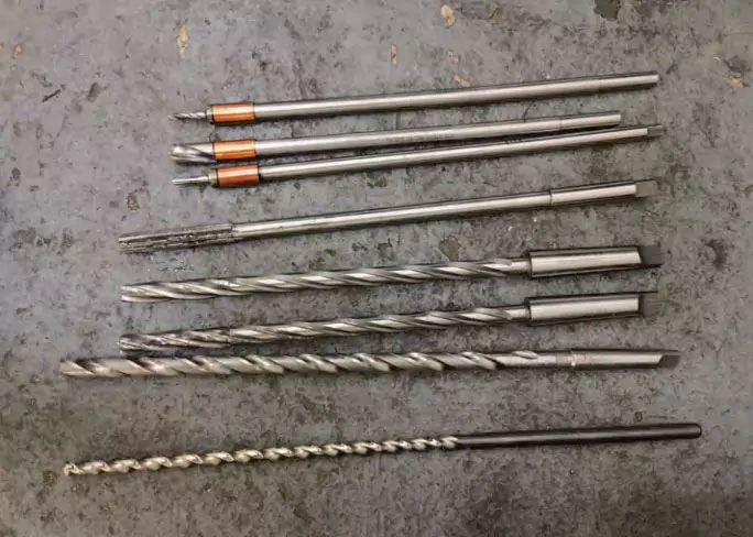
Figure 5 Tooles
The tool size is selected based on the reamed hole’s expansion allowance. After drilling with a φ15 mm drill bit, a two-cutter expander is used to correct hole straightness. The reaming sizes for the three passes are as follows:
15.67 (-0.05/-0.10) mm, 15.77 (0/-0.025) mm and 15.89 (0/-0.015) mm.
The diameter of the first reaming increased by 0.05-0.1mm; the diameter of the second reaming increased by 0.03-0.05 mm, and the reaming diameter increased by 0.01-0.02 mm.
The tool material selected is M42 high-speed steel.
The above tool parameters are selected, taking into account the tool angle and length of the stainless steel workpiece.
3.Determination of parameters and process flow
The process method selects the traditional method of drilling → reaming → reaming. The size of the pre-opened hole is φ10mm, and the hole is bored to φ12mm with a depth of 50mm.
The processed hole is used as a guide hole for reaming drilling and then reamed to φ15.67mm with a margin of 0.2mm, and manually reamed to a more stable size to improve the surface quality.
The choice of this process can control the straightness of the hole while ensuring dimensional accuracy.
The process program is below:
(1) Drill φ 10mm holes to a depth of 50mm.
(2) Boring to φ12(+0.03/+0.01)mm, length 50mm.
(3) Boring to φ12mm, recommended parameters: speed n=70r/min, feed f =0.09~0.11mm/r, feed speed v f=420~560mm/min.
(4) Bore to φ15.67(+0.02/0)mm, length 50mm.
(5) Bore to φ15.67mm, recommended parameters: speed n=70r/min, feed f=0.09~0.11mm/r.
(6) Bore to (φ15.77+0.02)mm, length 50mm.
(7) Bore to φ15.77mm, recommended parameters: speed n=70r/min, feed f=0.09~0.11mm/r.
(8) Bore to φ15.89(+0.02/0) mm, length 80mm.
(9) Clamp with manual reamer with lubricating oil. The reamer has a total blade length of 80 mm, which is relatively long. To ensure proper use, the rear 30 mm of the blade must be polished to remove excess material. A radial depth of 2 mm is selected, and the transition area is smoothed to improve cutting stability and surface quality.
(10) Manual reaming with 1.5 ° cutting cone reamer, and then 120 ° chamfering reamer for the bottom end of the hole reaming, the reamer blade length to shorten to 50 mm long, every 1 mm into the first, every half-turn into the first.
(11) Manual reaming shall not be reversed. When exiting, pay attention to try not to pour chips, reduce the number of feed, and strive to ream the hole in place. Do not allow halfway back to ream again. In case of jamming, we could reverse a little and then turn again.
(12) The initial hole’s ellipticity is about 0.1mm, and the largest place reaches 15.94mm, which makes the reaming process more laborious and hinders tool machining in the hole. We can solve this by reducing the length of the reamer blade and increasing the top tightening force.
(13) Machine tools should be used at the top of the manual reaming and the top of the 1mm step feed reaming. This procedure must be followed closely; otherwise, it is easy to skew.
(14) Manual reaming first 1.5 ° cutting cone reamer cutting, then 120 ° chamfering reamer for the bottom end of the hole reaming.
(15) The operator needs to use a φ 5.8mm special drill for drilling, with parameters set to a rotational speed of n=250r/min and a feed rate of f=0.024mm/r.
(16) We ream the φ 6mm hole by hand-made. When machining the φ 8mm inserted hole, we reduce the feed f to 0.012~0.02mm/r while keeping the rotational speed unchanged.
According to the test piece and the final size of the workpiece, the surface roughness value of the hole meets the requirement of Ra≤3.2μm, and the diameter of the hole is 15.91mm, which meets the requirements of the drawing.
Conclusion
We can draw the following conclusions based on the above analysis and actual processing.
(1) When processing a shaped receiver, the operator can perform deep hole drilling for boring and ordinary drilling, but the traditional method of drilling → expanding → reaming proves more reliable.
(2) Forming tools such as 120° double-edged reaming drills, φ 5.8mm extra-long drills and φ 6mm extra-long reamers are more suitable for processing stepped holes.
(3) When the drill is too long, the main cutting edge can be cut 1mm deep, thus reducing the tool’s cutting resistance and improving the chip-breaking efficiency.
(4) The parameters of the reaming drill in the machining process are: cutting speed vc=3~5m/min, feed f=0.09~0.11mm/r.
(5) The dimensional accuracy can be controlled at 0.02~0.03mm using the reaming method.