
The automotive industry is undergoing a major transformation. Smart manufacturing models remedy the inherent drawbacks of conventional automotive production.
These models boost productivity, product quality and production flexibility greatly. Mechatronics serves as a core pillar of smart manufacturing under such conditions.
It holds critical importance for vehicle production. The scope of its application directly shapes the smart manufacturing level of the automotive industry.
Smart automotive manufacturing raises strict requirements for process precision, coordination and inspection performance.
Mechatronics integrates diverse advanced technologies. It resolves many bottlenecks existing in traditional automotive manufacturing.
Practical applications still reveal several limitations at present. Low control accuracy, unstable bus communication and incomplete detection loops appear frequently.
Unreasonable production line layouts also restrict development. These problems slow the large-scale popularization of automotive smart manufacturing.
Researchers need to explore mechatronics applications thoroughly. They should refine technical schemes and build full-function test platforms.
These efforts accelerate deep fusion between mechatronics and all links of automotive smart manufacturing. They further push the transformation and upgrading of the automotive manufacturing sector.
Core Concepts and Technical Requirements of Intelligent Automotive Manufacturing
Mechatronics, the Internet of Things (IoT) and big data support intelligent automotive manufacturing. Manufacturers deploy this intelligent production method across the whole automotive workflow.
It covers vehicle design, manufacturing, testing and assembly. This production mode targets four core goals. Operators pursue automation, precision, flexibility and coordination in production activities.
The technology dismantles isolated barriers between separate manufacturing stages. It builds unified management throughout the whole supply chain.
In terms of intelligent automotive manufacturing, the primary technical focus lies in three areas:
(1) Motion precision must achieve micron-level position and path control to meet the high-precision production and installation requirements of automotive parts;
(2) Collaborative capabilities must enable effective communication and coordination among various production subsystems, machines, and systems to ensure the smooth progression of the production process;
(3) Precise inspection capabilities must provide continuous monitoring and timely feedback throughout the entire manufacturing process to enable online detection and real-time resolution of issues.
Key Points on the Application of Mechatronics Technology in Intelligent Automotive Manufacturing
Optimization of Multi-Axis Servo Drive and Motion Control Accuracy
Automakers are continuously tightening requirements for motion control accuracy, covering both precision machining of automotive components and vehicle assembly.
Engineers integrate multi-axis servo drive technology with high-precision motion control by selecting appropriate control strategies and hardware configurations, which improves motion control accuracy in automotive manufacturing and meets the stringent standards for precision machining and assembly.
1. Three-Closed-Loop Control Architecture for Multi-Axis Servo Systems
Servo motors cooperate with multi-axis servo drives, and each motion axis carries an independent servo drive.
The system adopts a three-closed-loop control scheme consisting of current, speed and position loops.
The current loop has a sampling time of ≤10 μs, the speed loop adjusts within 50–200 μs, and the position loop requires 250–1000 μs for trajectory tracking.
These parameter settings ensure synchronous and stable operation of all axes.
2. Iterative Learning Control for Motion Error Compensation
To further improve motion control accuracy, we must establish a motion error compensation model and adopt an iterative learning control method, with the core equation as follows:
uk+1(t)=uk(t)+Lek(t)
In the equation, uk+1(t) is the control variable (e.g., the current reference value for the q-axis) during the k+1st iteration; uk(t) is the control variable during the kth iteration;
L is the iteration gain (typically selected from the range of 0.01 to 0.05); ek(t) is the trajectory tracking error during the kth run, i.e., ek(t) = r(t) − yk(t), where r(t) is the predefined target trajectory;
yk(t) is the actual trajectory result obtained during the kth run.
3. Parameter Configuration of the High-Precision Servo Control System
At the same time, we must properly configure the relevant parameters of the servo system;
we select an optical encoder with a resolution of 2,500 lines to ensure that the position measurement accuracy reaches ±0.001 mm;
The rated speed of the servo motor is set to 1500 r/min, with a rated torque of 18 N·m, to ensure stable motor operation and sufficient power.
In addition, we must adjust the motion controller parameters: we adopt a PI controller with feedforward for the speed loop, setting the proportional gain from 5.0 to 8.0 and the integral time from 0.1 to 0.3 s;
The position loop employs P/PI control combined with acceleration feedforward, with the proportional gain ranging from 3.0 to 6.0, which effectively resists disturbances and ensures smooth acceleration and deceleration.
Coordinated Integration of In-Vehicle Buses and Industrial Field Buses
Automotive smart manufacturing links different production units, devices and control systems. Smooth data exchange removes isolated information barriers across the workshop.
Manufacturers build coordination mechanisms between onboard buses and industrial field buses. Engineers optimize bus communication protocols and structural layouts.
These upgrades deliver timely, reliable and accurate data transmission. The whole workflow also lifts collaboration efficiency on the production line.
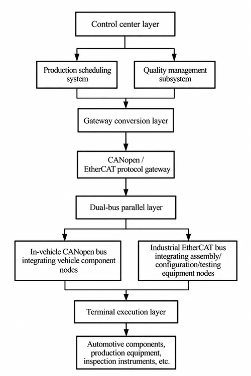
Designers apply a layered coordination strategy for bus networking. They define distinct functions and communication ranges for each bus category.
The layout forms a four-tier architecture. The tiers ascend from the in-vehicle bus layer to the gateway conversion layer, the industrial fieldbus layer, and finally the control center layer.
CANopen buses serve the in-vehicle bus layer. They transmit data among different vehicle components at 500 kb/s. Communication latency stays below 10 ms. EtherCAT buses support the industrial fieldbus layer.
These links connect production equipment and detection instruments at 1 Gbps. Their latency remains under 1 μs. Fast, stable transmission keeps multiple devices running synchronously.
Additionally, we can install a dedicated bus gateway to facilitate protocol conversion and information exchange between the in-vehicle bus and the industrial fieldbus.
Engineers design this gateway for two-way protocol conversion. It translates data between CANopen and EtherCAT. The device carries an object dictionary that follows DS301 and DS302 standards.
Technicians build mapping relationships for communication parameters. These links connect the parameters with PDOs and SDOs. PDOs handle data that demands fast response, such as temperature and voltage signals.
SDOs take charge of equipment parameter setup and fault diagnosis. Figure 1 illustrates the bus-cooperative integration architecture.
Machine Vision and Closed-Loop Control for In-Line Inspection
As the demands for product quality in intelligent automotive manufacturing continue to rise, it is necessary to establish a closed-loop control system based on machine vision and in-line inspection.
By leveraging mechatronics technology, this system enables high-precision, real-time inspection and feedback during the manufacturing and assembly of automotive components, thereby reducing production errors and improving product quality.
In practice, high-quality industrial cameras and laser sensors must be used to construct machine vision inspection equipment.
The camera has a resolution of 2048×1536 and a frame rate of 30 fps, while the laser sensor has a measurement accuracy of ±0.01 mm and a measurement range of 50–200 mm, ensuring the accuracy and efficiency of the inspection.
At the same time, machine vision inspection algorithms must be optimized by employing AI-based image recognition algorithms to detect dimensional deviations and surface defects, and other issues.
The requirements are a detection coverage rate of ≥98%, a common defect recognition rate of ≥90%, and a false positive rate of ≤1%.
Additionally, the system can be equipped with various types of LED line light sources to enhance inspection performance under different lighting conditions.
Implementation of a closed-loop inspection process: When machine vision detects a quality issue in a part, it immediately transmits the error information to the motion control system.
The motion control system then adjusts the corresponding servo motor parameters based on this information to correct production deviations,
The error correction response time is controlled within 100 ms, ensuring smooth production.
The main technical specifications of the machine vision in-line inspection system are shown in Table 1.
表1
Coordinated Scheduling of Electromechanical, Hydraulic, and Pneumatic Systems in Flexible Production Lines
Intelligent automotive manufacturing requires the implementation of flexible production to meet the demands of producing multiple vehicle models in small batches.
Flexible production lines require unified scheduling for electromechanical, hydraulic and pneumatic subsystems. Designers merge mechanical transmission, electrical control, hydraulic drive and pneumatic control technologies.
This fusion refines scheduling strategies for workshop operations. It raises the flexibility and coordination ability of flexible production lines.
1. Integrated Scheduling Framework Based on PLC and IIoT
A PLC acts as the core of this scheduling framework. The Industrial Internet of Things (IIoT) supports its data interaction. Operators manage on-site equipment including motors, hydraulic pumps and pneumatic valves under one platform.
The scheduling frequency is set to 50 ms to ensure that scheduling commands are issued in a timely manner.
In practice, the hydraulic system employs a variable-displacement pump with an operating pressure range of 16–25 MPa and a flow rate adjustable between 0 and 100 L/min.
Precise control of flow and pressure is achieved through electro-hydraulic proportional valves, with a regulation accuracy of ±0.5 MPa;
The pneumatic system uses an oil-free air compressor, with an operating pressure range of 0.6–0.8 MPa and an air delivery rate of 1.2 m³/min.
Solenoid valves provide precise control over the pneumatic actuators, with a response time of ≤20 ms.
2. Multi-Objective Optimization Scheduling Algorithm
Tuners refine the scheduling algorithm for electromechanical, hydraulic and pneumatic integration. This tuning targets a multi-objective optimization function. The function pursues three core goals simultaneously.
It shortens production cycles, lifts equipment utilization and cuts energy consumption.
minf=pe(em+ec)+ptmaxi,n(tci,n)
In the equation,
- f represents the total cost of joint scheduling;
- pe represents the price per kilowatt-hour;
- em is the energy consumption of mechanical equipment and electrical systems;
- ec is the energy consumption of hydraulic and pneumatic systems;
- pt is the cost per unit of time;
- tci,n is the processing time for the nth process step in the i-th production unit.
3. Digital Twin and Adaptive Adjustment of Flexible Production Lines
At the same time, digital twin technology is introduced to build a simulated digital twin on the flexible production line.
Simulation and optimization are performed prior to implementing the scheduling plan to ensure that the plan is generated in less than 8 seconds and contains no conflicts.
Furthermore, a self-adaptive adjustment module must be configured for the production line. Product replacement triggers parameter adjustment across the production line.
The system recalibrates mechanical, electrical, hydraulic and pneumatic components automatically. All switching operations finish within three minutes. Fast adjustments let the production line adapt rapidly to varied manufacturing targets.
Practical Applications and Results
Experimental Design and System Setup
Researchers test the performance of mechatronics technology for automotive smart manufacturing. They run trials on an experimental platform for intelligent auto-component production.
Automotive transmission housing precision machining and assembly serve as the test object. Four modules build up this complete experimental platform.
These modules include a multi-axis servo machining unit, a bus coordinated control unit, a machine vision inspection unit, and a flexible production line scheduling unit.
The platform adopts the following hardware setups. Eight servo drives and matching servo motors form the multi-axis servo system. 2500-line optical encoders attach to these motion units.
CANopen vehicle buses and EtherCAT industrial field buses support data communication. Special protocol gateways enable data conversion between these two bus types.
A 2048×1536 pixel industrial camera and laser sensor compose the vision inspection subsystem. The flexible production line carries a PLC controller, a variable-displacement hydraulic pump and an oil-free air compressor.
This experiment applies the mechatronics scheme proposed in the article. Technicians tune parameters of the multi-axis servo control system.
They refine bus coordination logic and raise detection precision for machine vision. Updated scheduling algorithms also streamline operation on the flexible production line.
We compared production accuracy, production efficiency, and product yield rates before and after implementation to the effectiveness of this method was verified.
For this trial, 100 transmission housings were selected as production samples, and the following test criteria were established:
Machining dimensional tolerance ≤ ±0.01 mm, production cycle ≤ 60 seconds per unit, and product yield rate ≥ 98%.
Experimental Data Acquisition and Precise Measurement
A multi-channel data acquisition system supports this test. It captures real-time operational and production data from every bench module.
The sampling rate stays at 10 samples per second. This setting guarantees reliable and complete data records.
Collected information covers multiple categories. Readings include trajectory errors, speeds and torque values of the multi-axis servo motors.
Operators also record bus communication delay and packet transmission success rates. Vision tests supply inspection precision and defect detection ratios.
Flexible line outputs track production cycles, equipment usage and energy consumption. Final measurements capture dimensional tolerances, assembly precision and overall quality of transmission housings.
The CRC algorithm checks all incoming data. It validates data integrity and accuracy. Workers build structured data logs and store them in time. Saved datasets lay foundations for follow-up analysis.
Inspection workflows merge two checking methods. Machine vision and manual inspection work together. They examine housing dimensions, surface conditions and assembly precision thoroughly.
Analysis of Experimental Results and Recommendations for Optimization
The collected experimental data were organized and summarized; key performance indicators were compared
before and after the application of mechatronics technology to draw conclusions from the experiments and propose optimization recommendations addressing the issues identified during testing.
Experimental results reveal clear performance gains after mechatronics integration. Machining path errors for automotive transmission housings stay within 0.6 μm.
Dimensional errors do not exceed ±0.008 mm. These figures satisfy relevant design specifications. Bus communication latency remains below 1 μs. The system achieves a 100 percent success rate for data transmission.
Machine vision covers 98.5 percent of inspection targets. Its defect detection rate hits 92 percent, while the false positive rate drops to 0.8 percent or lower.
Each workpiece takes 55 seconds to finish on the flexible production line. Equipment utilization reaches 88.5 percent. Total energy consumption falls by roughly 12 percent.
Finished products reach a pass rate of 99.2 percent. This value far exceeds the benchmark recorded before the technical upgrade. Table 2 lists all detailed comparison indicators.
表2
Based on an analysis of the experimental process and results, current mechatronics technology still faces numerous challenges in practical applications.
For example, slight trajectory errors accumulate after prolonged operation of multi-axis servo systems; The machine vision inspection system’s ability to detect minute defects still has room for improvement;
And the response speed of flexible production line scheduling when switching between different vehicle models could be further accelerated.
To address these issues, the following optimization recommendations are proposed:
(1) Install an error self-adaptive compensation module in the multi-axis servo system to perform error adjustments every 100 units produced, ensuring stable control accuracy;
(2) Improve the machine vision inspection algorithm by adding an image enhancement step to enhance the detection capability for minor defects;
(3) Optimize the flexible production line scheduling method by incorporating deep learning technology to forecast production demand, thereby reducing the time required for model changeovers and further enhancing the effectiveness of mechatronics
technology in the automotive manufacturing industry.
Conclusion
Mechatronics technology serves as a crucial foundation for intelligent automotive manufacturing.
Its applications in multi-axis servo drives, bus integration, machine vision inspection, and flexible production line scheduling can effectively enhance the production precision, collaborative efficiency, and product quality of intelligent automotive manufacturing.
The test results have validated the feasibility and effectiveness of this technology’s application.
The deep integration of mechatronics technology with intelligent automotive manufacturing is an inevitable path for the automotive industry’s development toward digitization and intelligence.
Practitioners will update technical schemes continually for future deployment. They adjust these plans to tackle new problems emerging from field applications. Refined collaborative control strategies boost the overall integration level.
R&D teams also expand investment in technology exploration. Extra research pushes deeper fusion between mechatronics and emerging tools.
These modern tools include the Internet of Things (IoT) and big data platforms. Full exploitation of this technology strengthens its core value in smart auto production.
Such progress steers China’s auto manufacturing sector toward high-end and intelligent growth.