
Horizontal machining center worktables are a cornerstone of modern high‑end manufacturing. They act as the core functional component that connects workpieces to the machine tool.
They also form the foundation for the machine’s overall geometric accuracy and dynamic performance.
Key features of this component—such as large circular bore systems and precision end faces—are subject to extremely tight geometric tolerance requirements and stringent surface quality standards;
The quality of their machining directly determines the machine tool’s ultimate overall performance and service life.
However, for a long time, the manufacturing processes for such large-sized, high-precision components have faced significant challenges.
Due to limitations in in-house machining capabilities, key manufacturing processes have often had to rely on outsourced machining.
Consequently, this model leads to persistently high production costs. It also brings lengthy supply chain lead times. More critically, it creates reliance on external sources for core manufacturing technologies and quality control systems.
This situation drives up production costs. It extends supply chain lead times as well.
Meanwhile, the quality of core processes becomes subject to external factors. This turns into a key bottleneck.
The bottleneck constrains a company’s autonomous production capacity and competitiveness.
This study aims to overcome the above-mentioned bottleneck. It also intends to realize cost reduction, efficiency improvement and autonomous quality control.
For these purposes, this paper proposes and implements an innovative in-house machining process.
Engineers develop the process based on the DiXi510 high‑precision horizontal CNC coordinate boring machine.
The core of this solution lies in the innovative application of reverse boring technology to address the challenge of machining the outer cylindrical end face of the workpiece;
High-precision specialized fixtures were also designed to ensure positioning accuracy and clamping stability during the machining process.
This paper aims to systematically elaborate on the design philosophy and implementation process of this process solution.
It verifies the machining results by means of a coordinate measuring machine (CMM).
It ultimately assesses its remarkable benefits. These benefits cover improved product quality, shortened production cycles and lower overall costs.
It is expected to offer valuable references for the machining and manufacturing of comparable high precision components.
Part Structure and Machining Requirements
The worktable, a key component of the horizontal machining center, has external dimensions of 1,000 mm × 1,000 mm × 237 mm.
After operators complete preliminary processing, they remove most of the roughing allowances on the workpiece’s internal cavity and outer cylindrical surfaces, and advance the part to the finishing stage.
This machining process focuses on the final shaping of a set of high-precision mating surfaces. It covers multiple key geometric features.
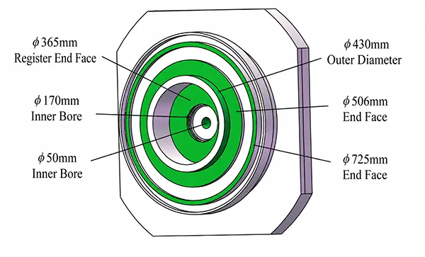
These features include the φ430 mm outer cylindrical surface, the φ506 mm and φ725 mm annular end faces, the φ50 mm and φ170 mm precision bores, as well as the φ365 mm shoulder end face.
These areas not only require precise control of dimensional tolerances but are also subject to stringent geometric tolerance constraints;
They must simultaneously ensure extremely high coaxiality, perpendicularity, and parallelism, as well as excellent surface quality.
The design arranges multiple finishing areas across different spatial planes. These areas feature strong mutual positional dependencies.
For this reason, process-triggered deformation of the machining system and clamping stresses generated during machining may readily give rise to accuracy deviations.
Therefore, this stage represents the most challenging and technically demanding core step in terms of accuracy control throughout the entire part manufacturing process.
Selection of Machining Equipment
Previously, external contractors had always machined the circular holes and end faces on this batch of large components.
To further enhance production autonomy, shorten supply chain lead times, and strengthen quality control over core processes, the company decided to bring this process in-house.
Since the workpieces consist of circular holes and end faces on large components with substantial dimensions, the equipment must meet high requirements for load-bearing capacity and machining range;
These holes and end faces act as critical reference points for subsequent assembly and functional performance.
Therefore, their dimensional accuracy must meet strict requirements.
So do their geometric tolerances, including coaxiality, perpendicularity and flatness. Their surface quality is also held to rigorous standards.
Engineers selected the DiXi510 high‑precision horizontal CNC coordinate boring machine as the machining equipment primarily because of its outstanding advantages in the following areas.
Ample Working Area and Travel
This machine is equipped with a large-size worktable. Its dimension reaches 1,800 mm × 1,350 mm.
It also delivers an extra-long worktable travel. The longitudinal travel is 1 000 mm, and the transverse travel is 2 000 mm.
These specifications fully satisfy the holding and machining requirements of this large-sized workpiece.
The spindle has a maximum stroke of 400 mm. It offers sufficient Z-axis space for deep-hole machining and multi-step face machining.
Operators can therefore complete multiple machining operations within one single setup. This effectively avoids cumulative errors originating from repeated re‑clamping.
Outstanding Machining Precision and Stability
The DiXi510 high-precision horizontal CNC coordinate boring machine belongs to high-precision coordinate boring equipment.
It can readily satisfy and surpass all drawing-defined technical requirements.
These requirements involve hole diameter, roundness, and positional accuracy. They also include end-face flatness and perpendicularity.
Advantages of Reverse Boring Technology
①Capable of machining external cylindrical surfaces.
Reverse boring employs a reverse feed method to achieve efficient machining of external cylindrical end faces, solving the problem posed by traditional boring—where tool structure limitations prevent direct machining of such areas.
② Reduced machining costs.
Reverse boring helps simplify the overall process flow. It cuts down the required types of cutting tools and auxiliary equipment.
It also removes the necessity for external subcontracting for machining work. This consequently lowers production costs.
Previously, the machining of large circular holes and end faces was outsourced externally.
The company transfers such work to in-house production instead. It selects the DiXi510 high-precision horizontal CNC coordinate boring machine as the processing equipment.
On this basis, the company guarantees high-quality completion of the present machining task. Meanwhile, it establishes a solid foundation.
This foundation supports future machining assignments for higher-precision and more complex large-sized components.
This represents a key initiative in enhancing the company’s core competitiveness.
Selection of Cutting Tools and Inspection Equipment
Single-edge boring bars with diameters of 50 mm, 170 mm, and 430 mm are used to machine hole systems of different diameters, respectively.
Additionally, 80 mm and 125 mm face milling cutters are used for milling the relevant surfaces.
To ensure machining quality, technicians have implemented a comprehensive inspection system.
To verify dimensional accuracy, technicians take precision measurements using an outside micrometer, a three‑jaw inside micrometer, and an inside micrometer dial gauge;
For specific contours, ring gauges are used for rapid verification; finally, a coordinate measuring machine (CMM) performs a comprehensive verification of geometric tolerances.
Clamping and Positioning Methods
Overall Structural Design of the Specialized Fixture System
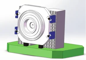
To address the challenges of inconsistent positioning references and clamping deformation during workpiece machining, we designed a specialized fixture system that integrates positioning, clamping, and auxiliary support functions.
The core of the jig’s structural design lies in the manufacturing process of its precision positioning reference surface, which integrates four self-milled precision support blocks.
This manufacturing method ensures high precision in the shape, dimensions (height), and relative positions of the support blocks, thereby providing the worktable with a highly rigid and precise positioning reference surface.
For the clamping system design, a four-point bent-plate clamping mechanism was combined with two precision support blocks.
This layout not only enables precise positioning of the workpiece but also provides reliable clamping force through optimized force distribution.
This ensures the worktable is securely mounted on the dedicated fixture, effectively suppressing micro-movement and deformation during machining, and lays a solid foundation for ensuring the final machining quality of the components.
The worktable clamping setup is shown in Figure 1.
Positioning and Clamping Restraint Principle of the System
This clamping system achieves complete positioning and clamping of the workpiece through the following methods.
1) Support blocks (4): Restrict movement in the Y-direction.
2) Support blocks (2 at the bottom) + the worktable’s own weight: Restrict movement in the Z-direction.
3) Four-point bending plate clamping: Restrict rotation in the Z-, X-, and Y-directions.
4) Bending plate clamping + support blocks + self-weight: work together to reinforce the restriction of rotation in the X and Y directions.
5) Bending plate clamping + friction: assist in restricting movement in the X direction.
Technical Advantages and Engineering Application Value of the Clamping Solution
This innovative clamping solution offers multiple advantages: through the synergistic effect of multi-point clamping and rigid support, it virtually eliminates any displacement or vibration that may occur during machining;
The optimally designed positioning system builds an accurate process reference for subsequent operations.
It enables the machining of key structural features. These features include connection holes and cavities.
The process can thus meet their higher‑level dimensional accuracy and geometric tolerance requirements.
This clamping approach greatly boosts machining efficiency. It can complete multiple machining procedures within a single setup.
It guarantees positional accuracy among different machined features. Meanwhile, it prevents error accumulation induced by repeated positioning.
Accordingly, it delivers dependable process assurance for high-quality and high-efficiency mass production.
Machining Process
Machining Objective: To machine internal bores, external circles, and end faces of various sizes on the worktable of a CNC machine tool.
The main machining areas of the worktable are shown in Figure 2.
Although technicians employ precision machining equipment, they still adopt the “rough-to-finish” machining method throughout the machining process.
Standard boring and milling cutters are used for machining from the inside out;
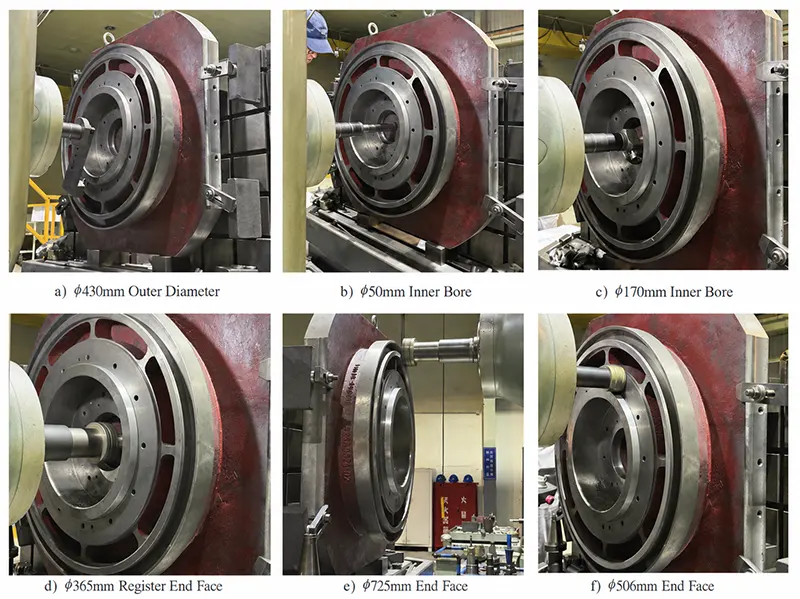
However, to machine the outer cylindrical end face, operators must mount the tool in the opposite direction to perform boring and milling of the outer cylinder‑a process known as reverse boring.
The machining sequence for the worktable is shown in Figure 3.
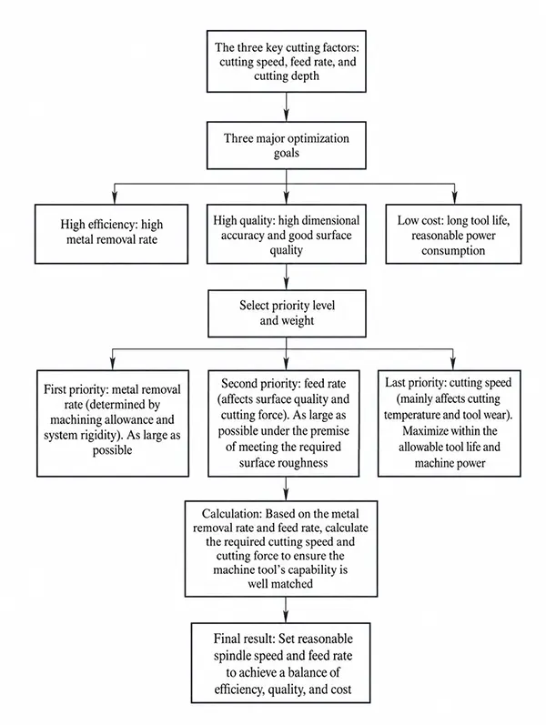
The three cutting parameters are not independent of one another; together, they determine the efficiency, quality, and cost of the cutting process, and the principles guiding their selection are of critical importance.
Figure 4 illustrates the general logic and interrelationships involved in selecting the three cutting parameters.
For each machining step, technicians select the appropriate spindle speed, feed rate, and tool diameter based on specific dimensions and requirements, and carry out the corresponding calculations using the relevant formulas.
vc=πDn/1000 (1)
In the equation, vc is the cutting speed (m/min); D is the tool diameter (mm); and n is the spindle speed (r/min).
vf=fn (2)
In this equation, vf is the feed rate (mm/min); f is the feed per revolution (mm/r); and n is the spindle speed (r/min).
The process parameters for rough machining and finish machining are shown in Tables 1 and 2, respectively.
| Machining Operation | n (r/min) | v₍c₎ (m/min) | D (mm) | f (mm/r) | v₍f₎ (mm/min) |
|---|---|---|---|---|---|
| φ430 mm Outer Diameter | 100 | 135 | 430 | 0.10 | 10 |
| φ50 mm Inner Bore | 350 | 55 | 50 | 0.06 | 20 |
| φ170 mm Inner Bore | 245 | 130 | 170 | 0.08 | 20 |
Table 1 Rough Machining Process Parameters
| Machining Operation | n (r/min) | v₍c₎ (m/min) | D (mm) | f (mm/r) | v₍f₎ (mm/min) |
|---|---|---|---|---|---|
| φ430 mm Outer Diameter | 130 | 175 | 430 | 0.06 | 8 |
| φ50 mm Inner Bore | 350 | 55 | 50 | 0.05 | 16 |
| φ170 mm Inner Bore | 245 | 130 | 170 | 0.07 | 16 |
| φ365 mm Register End Face | 350 | 137 | 125 | 0.40 | 150 |
| φ725 mm End Face | 350 | 137 | 125 | 0.40 | 150 |
| φ506 mm End Face | 400 | 100 | 80 | 0.40 | 150 |
Table 2 Finishing process parameters
Inspection Results
Accuracy inspections were conducted on the finished worktable using a coordinate measuring machine (CMM) to focus on measuring the flatness of the worktable’s reference surface, as well as the parallelism, perpendicularity, coaxiality, and surface roughness of the mounting surfaces, along with the machining accuracy of critical dimensions.
The inspection results are shown in Table 3.
| Inspection Item | Requirement | Part No. 1 | Part No. 2 | Part No. 3 | Part No. 4 |
|---|---|---|---|---|---|
| Lower Limit Deviation of φ430 mm Outer Diameter | −0.04 | −0.036 | −0.038 | −0.036 | −0.035 |
| Upper Limit Deviation of φ50 mm Inner Bore | 0.025 | 0.0105 | 0.0215 | 0.0132 | 0.0142 |
| Upper Limit Deviation of φ170 mm Inner Bore | 0.04 | 0.0146 | 0.0116 | 0.0039 | 0.0067 |
| Concentricity of φ170 mm Inner Bore | 0.01 | 0.0080 | 0.0076 | 0.0053 | 0.0060 |
| Perpendicularity of φ170 mm Inner Bore | 0.01 | 0.0080 | 0.0006 | 0.0013 | 0.0007 |
| Parallelism of φ170 mm Register End Face | 0.01 | 0.0066 | 0.0042 | 0.0056 | 0.0066 |
Table 3. Test Results (Unit: mm)
The test results show that the machining errors for all critical dimensions are within the allowable limits, and the overall accuracy meets the required standards, thereby validating the effectiveness and reliability of the machining process used in this operation.
Conclusion
This paper focuses on the specific applications of counter-boring technology in the machining of cylindrical surfaces and end faces.
It expands the machining capabilities of CNC coordinate boring machines and includes the design of high-precision specialized fixtures to ensure workpiece positioning accuracy and clamping stability, thereby improving product quality and shortening production cycles.
The findings are summarized as follows.
Process Innovation
The reverse boring technique using boring and milling cutters enables the machining of the outer end face of workpieces.
This overcomes the limitation of traditional boring and milling cutters, which could only machine inner circles, thereby expanding the machining range and improving machining efficiency.
The specialized fixture design uses four support blocks to achieve high-precision positioning and clamping of the worktable, providing a reliable reference for subsequent machining.
The use of the specialized fixture and reverse boring technique ensures machining accuracy and surface quality.
Accuracy Verification
Accuracy tests were conducted on the machined worktable using a coordinate measuring machine.
The results showed that all parameters met the design requirements, verifying the effectiveness of the innovative process.
Economic Benefits
By adopting the reverse boring technique using a boring and milling cutter, we have addressed the cost issue associated with outsourcing or purchasing specialized equipment.
This approach saves approximately 20,000 yuan per part, resulting in cumulative savings of nearly 1 million yuan for a batch of 50 parts, yielding significant economic benefits.
Application Prospects
This technology can be applied to the machining of deep-cavity outer circles in one-piece die-casting molds for typical components in the new energy vehicle sector, as well as the inner bosses of electric motor housings.
By performing high-precision outer-circle milling directly within enclosed structures, it eliminates the need for secondary clamping and ensures the coaxiality and positional accuracy of critical mating surfaces.
Its core value lies in solving the challenges of precision machining of outer circles and end faces on large, complex structural components within enclosed or confined spaces, demonstrating extremely broad application prospects.
The use of boring-milling cutters for reverse boring and specialized fixtures enables efficient, high-precision machining on CNC machine tool tables while effectively reducing machining costs, offering significant practical value.