
Serpentine traces—those winding, snake-like paths on printed circuit boards—are among the most recognizable yet frequently misunderstood features in high-speed PCB design.
Although widely used for length matching in DDR memory interfaces, these techniques serve purposes far beyond basic delay compensation, including phase alignment, differential signal integrity maintenance, and electromagnetic compatibility optimization.
However, serpentine routing is a double-edged sword: while it solves timing and skew problems, it introduces its own set of challenges, including impedance discontinuities, signal reflections, and near-end crosstalk.
This article examines the core functions of serpentine traces—from delay compensation in source-synchronous systems to phase correction in differential pairs—while also exploring the signal integrity trade-offs they impose.
It further provides practical R&D guidance on how to implement serpentine routing elegantly, balancing the need for timing alignment with the preservation of signal quality across different speed domains.
Application: Timing Matching
This is the most well-known function of serpentine traces.
In source-synchronous clock systems (such as DDRx), there are strict setup and hold time requirements between the data signal (DQ), the select signal (DQS), and the clock signal (CLK).
Since on-chip skew is extremely small, the primary source of delay variation stems from differences in PCB trace lengths.
In this scenario, serpentine routing serves as a means of delay compensation by increasing trace length to offset signal propagation delays.
Core Formula: Delay = Length × (1 / Vp), where Vp is the signal propagation speed in the dielectric.
R&D Perspective: We focus not on “length differences” but on “delay differences.”
During layout, it is essential to consider not only trace length but also the layer stackup.
The dielectric constants of inner layers (stripline) and outer layers (microstrip) differ, resulting in different propagation speeds.
Sometimes, an inner-layer trace must be 10% longer than an outer-layer trace for their delays to be equal.
Beginners often overlook this point.
Advanced: Phase Matching
In differential signals, intra-pair skew is even more critical than total length.
An ideal differential signal is completely symmetrical between the positive and negative ends, with opposite polarities.
If intra-pair skew becomes excessively large, part of the differential energy converts into common-mode noise.
This not only degrades signal quality but may also lead to EMI issues.
The role of serpentine traces here is to correct minor phase differences.
However, note that it is generally not recommended to route serpentine traces over large areas of a differential pair.
This is because serpentine traces alter the coupling state of the differential pair and introduce impedance discontinuities.
The correct approach is to prioritize phase correction through “small-amplitude, in-phase and out-of-phase” fine-tuning.
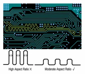
Core Pain Point: The Cost of Meandered Traces—Reflections and Crosstalk
This is what troubles R&D engineers the most. Meandered traces essentially “compromise” signal integrity.
Impedance Jumps and Reflections
In standard meandered traces (especially dense “W” or “U” shapes), the trace width actually increases at the corners (because the arc lengths on the inner and outer sides differ), which leads to a local decrease in impedance.
When a signal encounters such an impedance discontinuity, reflections occur.
Near-End Crosstalk (NEXT)
This is the most critical issue. When two parallel traces are too close together, mutual capacitance and mutual inductance increase dramatically.
If the spacing (S) between parallel segments of a serpentine trace is less than three times the trace width (the 3W rule), the longer the parallel segments, the more severe the crosstalk.
High-Frequency Pitfall: For GHz-level signals (such as PCIe 4.0/5.0), we would rather have a slightly larger length difference than ever use densely packed serpentine traces.
This is because severe crosstalk can cause the eye diagram to close completely.
Practical R&D: How to Route Snake-Like Traces Elegantly?
Since snake-like traces are a double-edged sword, we must be strategic when setting layout rules:
Control the parallel spacing (S)
Separate parallel routing segments by the maximum feasible distance.
Engineers generally recommend S ≥ 3W (where W denotes the trace width).
When layout space is severely constrained, maintain this rule in sensitive regions such as areas adjacent to clock traces.
Choose an Appropriate Coupling Method
Loose Coupling: Recommended. Increase the spacing between traces to reduce mutual capacitance and inductance.
Although this requires more area for routing, it is beneficial for signal quality.
Tight Coupling: Generally not recommended for serpentine routing, unless you have extremely strict requirements for space and immunity to interference and have verified this through simulation.
Optimize Corner Shapes
Avoid sharp 45° or 90° right angles. Use 45° bends or rounded corners;
This not only reduces impedance spikes but also lowers EMI radiation.
Avoid Sensitive Areas
Do not route serpentine traces beneath connectors, crystal oscillators, switching power supplies, or along the edges of shielding enclosures.
The magnetic field environment in these areas is complex, and serpentine traces are highly susceptible to acting as receiving antennas.
Segmented Compensation
Do not attempt to compensate for the entire length difference in a single run.
Use a “segmented compensation” strategy, incorporating small sections of serpentine routing at regular intervals.
This disperses the energy from reflections and crosstalk, preventing the formation of concentrated spikes.
Conclusion
Serpentine routing is not an end in itself, but rather a means of compromise.
Our ultimate goal is signal integrity (SI). When “equal length” conflicts with “quality,” we must learn to make trade-offs:
In low-frequency, low-speed buses (such as I2C and SPI), serpentine routing is generally unnecessary.
In medium- to high-speed buses such as DDR, serpentine routing is essential, but it must follow the principles of “wide spacing, short parallel runs, and multiple segments.”
For ultra-high-speed serial buses such as SerDes, designers minimize serpentine routing and utilize the chip’s internal CDR (Clock and Data Recovery) circuitry to cancel skew.
The next time you pick up your mouse to draw that bunch of “snakes,” take a moment to pause and ask yourself: Am I solving a timing problem, or am I creating a new signal integrity disaster?